

Rare Earth Laminated, Composite Magnets With Increased Electrical Resistivity
- Summary
- Abstract
- Description
- Claims
- Application Information
AI Technical Summary
Benefits of technology
Problems solved by technology
Method used
Image

Examples
example 1
[0094]Anisotropic Sm(Co, Fe, Cu, Zr)z / CaF2 laminated magnets with increased electrical resistivity were synthesized by regular powder metallurgical processes consisting of sintering at 1195° C., solution treatment at 1180° C. and aging at 850° C. followed by a slow cooling to 400° C. The total weight of each magnet was approximately 110 grams. The total amount of CaF2 addition in the laminated magnet was 1 weight % and there were 10 layers of CaF2. The following are the magnetic properties and electrical resistivity data:
Residual induction, Br: 10.6 kG
Intrinsic coercivity, Hci:>25 kOe
Maximum energy product, (BH)max: 25.1 MGOe
Electrical resistivity increased by 170% as compared to magnets without dielectric additions.
example 2
[0095]Anisotropic Sm(Co, Fe, Cu, Zr)z / CaF2 laminated magnets with increased electrical resistivity were synthesized by regular powder metallurgical processes consisting of sintering at 1195° C., solution treatment at 1180° C. and aging at 850° C. followed by a slow cooling to 400° C. The total weight of each magnet was approximately 110 grams. The total amount of CaF2 addition was 5 weight %. There were 10 layers of CaF2 distributed within approximately a quarter of the volume of the part, towards an end which was a magnetic pole. The following are the magnetic properties and electrical resistivity data:
Residual induction, Br: 8.7 kG
Intrinsic coercivity, Hci:>25 kOe
Maximum energy product, (BH)m: 17.5 MGOe
Electrical resistivity of the layered region increased by 244% as compared to magnets without dielectric additions.
example 3
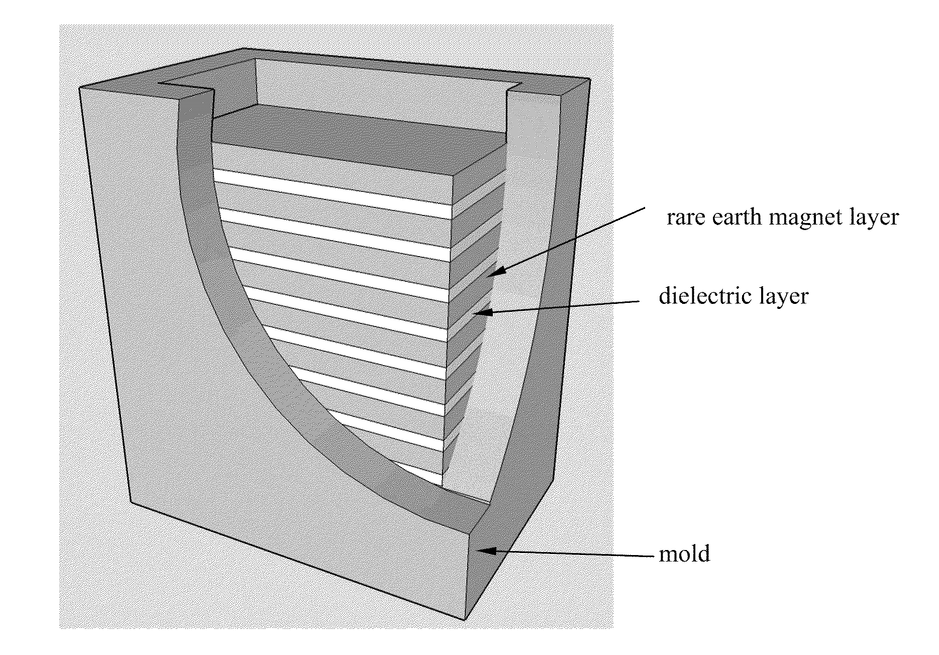
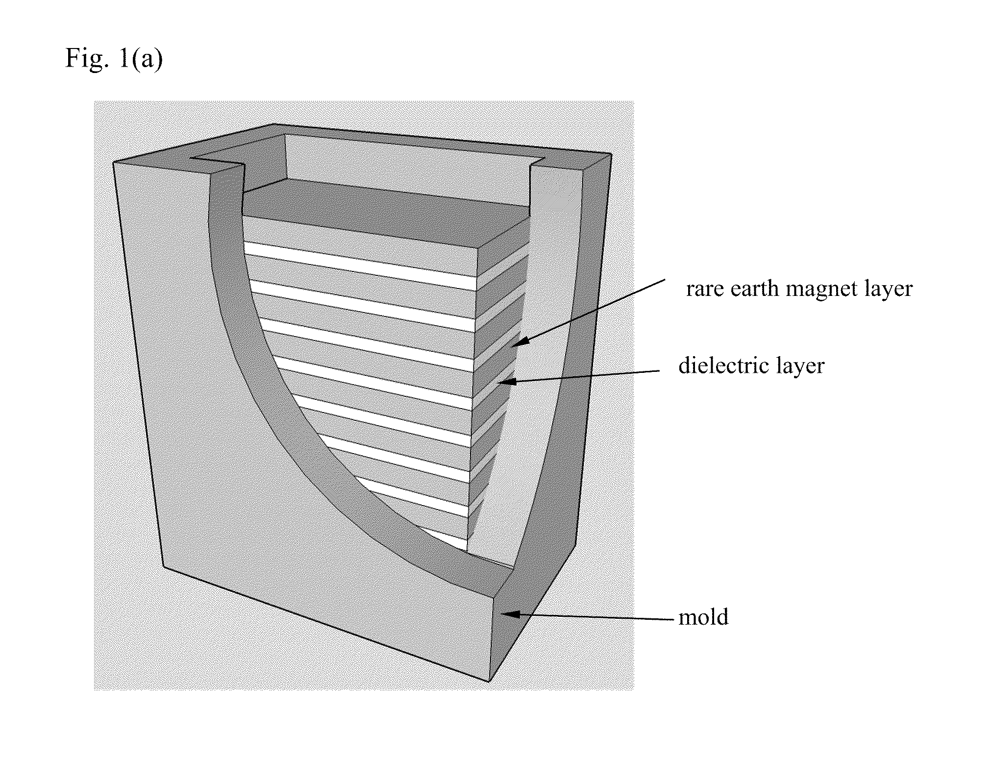
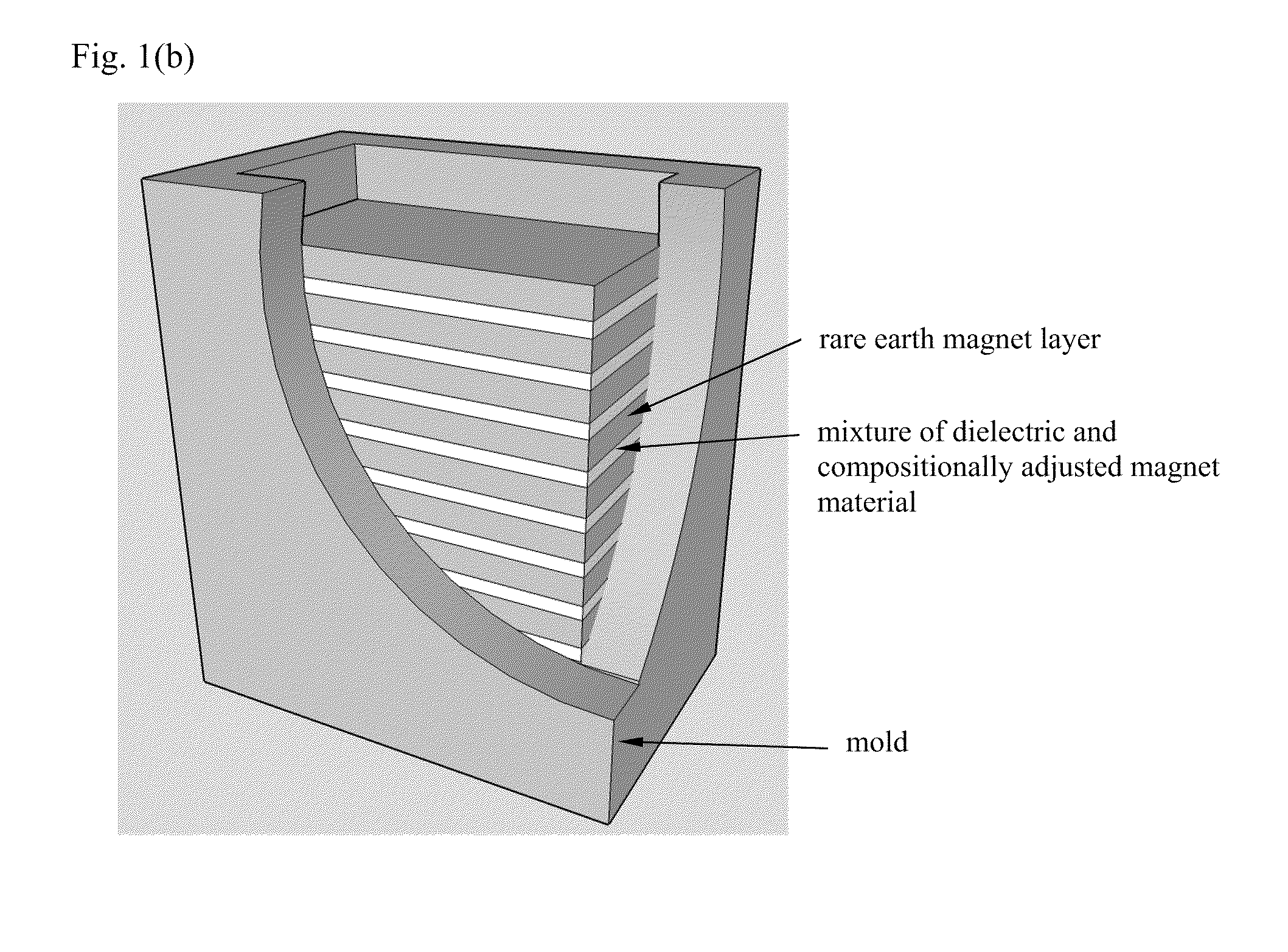
[0096]Anisotropic Sm(Co, Fe, Cu, Zr)z / CaF2 laminated magnets with increased electrical resistivity were synthesized by regular powder metallurgical processes consisting of sintering at 1195° C., solution treatment at 1180° C. and aging at 850° C. followed by a slow cooling to 400° C. The total weight of each magnet was approximately 425 grams. About 300 grams of magnet powder was added in the mold as a shell supported by non magnetic steels shims, leaving an empty core. Alternating layers of magnet powder and CaF2 were individually hand pressed into the cavity. The total amount of CaF2 distributed in 8 layers within the core region was 5 weight %. The following are the magnetic properties and electrical resistivity data:
Residual induction, Br: 9.1 kG
Intrinsic coercivity, Hci: >25 kOe
Maximum energy product, (BH)max: 19.7 MGOe
Electrical resistivity was infinite, suggesting that at least one layer assured a total electrical insulation.
[0097]The present invention is further described by...
PUM
| Property | Measurement | Unit |
|---|---|---|
| Percent by mass | aaaaa | aaaaa |
| Thickness | aaaaa | aaaaa |
| Thickness | aaaaa | aaaaa |
Abstract
Description
Claims
Application Information