CPP-GMR sensor with corrosion resistent spacer layer and higher signal/noise ratio

a gmr sensor and spacer layer technology, applied in the field of gmr sensors, can solve the problems of reducing the signal/noise ratio of cpp-gmr sensors, affecting the performance of gmr sensors, and affecting the reliability of gmr sensors, so as to increase the electrical resistivity of the read head sensor and increase the resistance to corrosion

Active Publication Date: 2013-02-28
WESTERN DIGITAL TECH INC
View PDF7 Cites 5 Cited by
  • Summary
  • Abstract
  • Description
  • Claims
  • Application Information

AI Technical Summary

Benefits of technology

[0010]Another embodiment of the present invention provides a method of fabricating a read head sensor. The method includes depositing a first magnetic layer onto a substrate. The method also includes depositing a spacer layer above the first magnetic layer. The spacer layer comprises a metallic alloy, of which at least one metal in the alloy is electrically conductive. Further, the spacer layer is (i) more resistant to corrosion and (ii) increases the electrical resistivity of the read head sensor, relative to a spacer layer consisting entirely of the at least one metal. The method includes depositing a second magnetic layer above the spacer layer.

Problems solved by technology

At these higher current densities, the output signal and signal / noise ratio for a CPP-GMR sensor is limited by spin-torque effects, which originate from the torque induced on either the free or reference magnetic layers by the spin-polarized electron current density applied during operation.
If too large, the spin-torque can introduce oscillatory instability of the magnetization in either the free or reference layers.
Moreover, during processing of a read head, a CPP-GMR sensor may be subjected to lapping or chemical mechanical polishing / planarization (CMP) during which exposed layers may begin to corrode.
The metallic spacer layer may be particularly susceptible to oxidizing during this process.
For example, common spacer layer materials are known to easily corrode or tarnish.
During a mechanical lapping process to form the air bearing surface (ABS), these materials may oxidize and hamper the electrical current flowing between the different layers of the CPP-GMR sensor.

Method used


Image

  • CPP-GMR sensor with corrosion resistent spacer layer and higher signal/noise ratio
  • CPP-GMR sensor with corrosion resistent spacer layer and higher signal/noise ratio
  • CPP-GMR sensor with corrosion resistent spacer layer and higher signal/noise ratio

Examples


example embodiments

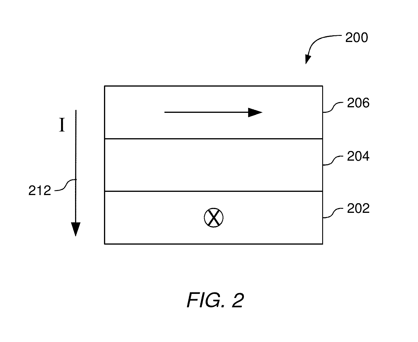
[0068]FIGS. 8A-C illustrate different read sensors, according to embodiments of the invention. FIG. 8A shows one embodiment of a read sensor that contains a CPP spin valve. A typical CPP-GMR spin valve is formed with a ferromagnetic free layer 806, a spacer layer 804, a pinned ferromagnetic reference layer 802, and an anti-ferromagnetic pinning layer 808. The ferromagnetic free layer 806 may comprise of the same material(s) that are suitable for the ferromagnetic reference layer 802. The ferromagnetic layers 802, 806 may comprise of the same material(s), or they may comprise a different single layer or multi-layer of alloys of, for example, Co, Fe and Ni.

[0069]FIG. 8B illustrates a pseudo spin valve where the ferromagnetic reference layer 802 is not pinned to an anti-ferromagnetic pinning layer.

[0070]FIG. 8C shows an “AP-pinned” spin valve where a pinned ferromagnetic layer 812 is exchange coupled to anti-ferromagnetic pinning layer 808, and is also anti-ferromagnetically coupled to...


PUM

PropertyMeasurementUnit
bias voltageaaaaaaaaaa
electrically conductiveaaaaaaaaaa
electrical resistivityaaaaaaaaaa

Abstract

A method and apparatus for increasing the electrical resistivity and corrosion resistance of the material forming a spacer layer in current-perpendicular-to-the-plane (CPP) giant magnetoresistive (GMR) sensors. The increased resistivity of the spacer layer, and thus, the CPP-GMR sensor permits a larger voltage across the sensor and a higher signal-to-noise ratio. The increased corrosion resistance of the spacer layer minimizes the effects of exposing the spacer layer to corrosive materials during fabrication. For example, adding tin to silver to form a metallic alloy spacer layer increases the corrosion resistance of the spacer layer and the electrical resisitivity of the CPP-GMR sensor relative to a spacer layer consisting solely of silver. The Ag—Sn alloy permits a larger current to flow through the sensor, which increases the signal-to-noise ratio.

Description

BACKGROUND OF THE INVENTION[0001]1. Field of the Invention[0002]Embodiments of the present invention generally relate to giant magnetoresistive (GMR) sensors. More particularly, the invention relates to current-perpendicular-to the-plane (CPP) magnetoresistive sensors.[0003]2. Description of the Related Art[0004]Magnetic read heads in modern magnetic disk drives operate on the basis of the tunneling magnetoresistive (TMR) effect in which a component of the read element resistance varies as the cosine of the angle between the magnetization in free and reference magnetic layers which sandwich an insulating tunnel barrier layer. Recorded data can be read from a magnetic medium because the external magnetic field from the recorded magnetic medium (i.e., the signal field) causes a change in the direction of magnetization in the free layer, which in turn causes a change in resistance across the tunnel barrier in the TMR and a corresponding change in the sensing electrical current or volta...

Claims


Application Information

Patent Timeline
Patent Type & Authority Applications(United States)
IPC IPC(8): G11B5/33B05D5/12
CPCG11B5/3906B82Y10/00G11B2005/3996Y10T428/1193
Inventor CHILDRESS, JEFFREY R.READ, JOHN C.SMITH, NEIL
Owner WESTERN DIGITAL TECH INC
Why Eureka
Try Eureka