Composite deelectric material and substrate

Inactive Publication Date: 2006-09-21
TDK CORPARATION
View PDF7 Cites 2 Cited by
  • Summary
  • Abstract
  • Description
  • Claims
  • Application Information

AI Technical Summary

Benefits of technology

[0014] For the purpose of solving the above described problems, the present inventor made various investigations, and found that inclusion of oxides of a transition metal element having a plurality of valences in a spherical dielectric ceramic powder is extremely effective in improving the electric resistivity. More specifically, the present invention provides a composite dielectric material comprising a

Problems solved by technology

The substrates made of dielectric materials are excellent in the properties of dielectric constant ε and tan δ, but have drawbacks in dimension accuracy and machinability, and have a problem that the dielectric substrates are so brittle that they are easily chipped and cracked.
On the other hand, the substrates made of organic materials such as resins and the like have the advantages of excellent moldability and machinability, and small tan δ, but have a problem that the dielectric constants ε are small.
For example, a powder produced from the liquid phase by means of such a method as a precipitation method is too fine to acquire the dispersion properties and packing properties for resin m

Method used


Image

  • Composite deelectric material and substrate
  • Composite deelectric material and substrate
  • Composite deelectric material and substrate

Examples


experimental example 1

[0133] An experiment carried out for checking the preferable additives for the dielectric ceramic powder will be described as Experimental Example 1.
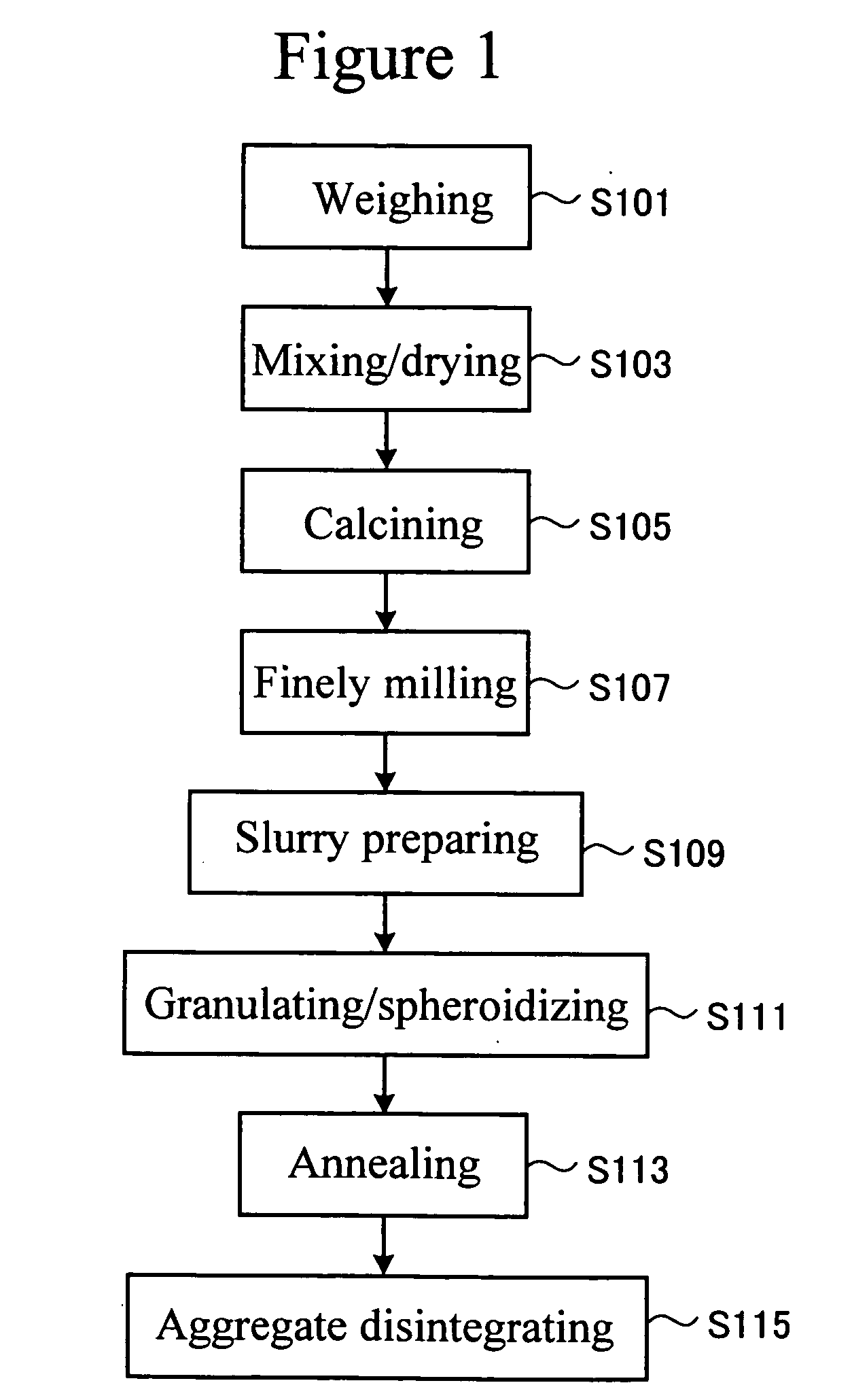
example 1

[0134] As starting material powders, a BaCO3 powder, a TiO2 powder and a Nd2O3 powder were prepared in an total amount of 1.5 kg, and mixed in pure water to prepare a slurry having a concentration of 60%. To 2.5 kg of this slurry, 30 cc of a dispersant (brand name: A-30SL (10% solution) manufactured by Toa Gosei Co., Ltd.) was added, and the mixture obtained was mixed by use of a ball mill at a rotation speed of 85 rpm for 16 hours. Then, the mixed material was dried for 24 hours, and thereafter calcined at 1225° C. in the air for 2 hours to yield a dielectric ceramics material. The dielectric ceramics material was converted into a slurry having a concentration of 60% by using water, and finely pulverized with a ball mill so as for the mean particle size thereof to be 0.4 to 1.5 μm. The slurry was dried to yield a dielectric ceramic powder. To the powder, MnCO3 was added as an additive in a content of 0.025 to 0.2 wt %, and then water was added to yield a slurry having a concentrati...

experimental example 2

[0157] An experiment carried out for checking the preferable addition amount in the case where MnCO3 is used as additive will be described as Experimental Example 2.

[0158] Dielectric ceramic powders were prepared in which the addition amount of MnCO3 was set at 0.025 wt %, 0.05 wt %, 0.1 wt %, 0.15 wt %, 0.2 wt %, 0.3 wt % and 1.0 wt %, respectively. Composite dielectric materials were prepared under the same conditions as in Example 1 except that the timing of the addition of MnCO3 and the annealing conditions were set as follows. An analysis of the compositions of the dielectric ceramic powders was conducted to confirm that BaO, Nd2O3, TiO2 and MnO were contained.

3>

[0159] Addition was made in the mixing / drying step (step S103).

[0160] Firing was conducted in the air at 1100° C. for 4 hours.

[0161] For each of the 7 composite dielectric materials, the electric resistivity was measured by means of the same method as described above. The results obtained are shown in FIG. 7. For th...


PUM

PropertyMeasurementUnit
Particle sizeaaaaaaaaaa
Frequencyaaaaaaaaaa
Specific surface areaaaaaaaaaaa

Abstract

An oxide of a transition metal element having at least two valences less than 4 is contained in a spherical dielectric ceramic powder. According to a composite dielectric material using the dielectric ceramic powder, the electric resistivity can be made to take such a high value as 1.0×10¹² Ω·cm or more while satisfactory dielectric properties are being maintained.

Description

TECHNICAL FIELD [0001] The present invention relates to a composite dielectric material suitable for use in a high frequency band and a substrate. BACKGROUND ART [0002] Recently, with rapid increase of communication information, reduction in size and weight, and speedup of communication appliances are eagerly demanded. Particularly, the frequency bands of the radio waves, for use in the fields of satellite communication and mobile communication based on portable terminals such as digital cellular phones and based on car phones, falls in a high frequency band ranging from the megahertz band to the gigahertz band (hereinafter, referred to as “GHz band”). [0003] In the rapid development of the communication appliances being used, downsizing and high density mounting have been attempted for the cases, substrates, and electronic elements. For the purpose of further promoting the reduction in size and weight of the communication appliances for the high frequency bands, however, the materi...

Claims


Application Information

Patent Timeline
IPC IPC(8): C08K3/22C08L101/00C08F16/22C08J5/10C08K7/18C08L29/10H01B3/00H01B3/12H05K1/02H05K1/03H05K1/16
CPCC08J5/10C08J2325/18C08K3/22C08L101/00H01B3/004H01B3/12H05K1/024H05K1/0373H05K1/162H05K2201/0209
Inventor ITAKURA, KEISUKEKANADA, ISAOCHIBA, IKUKAINOUE, MASAYOSHIOZAWA, MIOCHE, SHENGLEI
Owner TDK CORPARATION
Why Eureka
Try Eureka