
Health prognosis for complex system using fault modeling

a complex system and fault modeling technology, applied in the direction of fault response, instruments, structural/machine measurement, etc., can solve the problems of failures and faults that affect the operation of vehicles, types of devices and algorithms susceptible to errors, failures and faults that have a negative impact on the health of complex systems, and fault modeling has not been used to provide the prognosis for the future state of health of complex systems. , the ability to provide system health prognosis becomes more difficul

Active Publication Date: 2011-08-18
GM GLOBAL TECH OPERATIONS LLC
View PDF3 Cites 32 Cited by
  • Summary
  • Abstract
  • Description
  • Claims
  • Application Information

AI Technical Summary

Benefits of technology

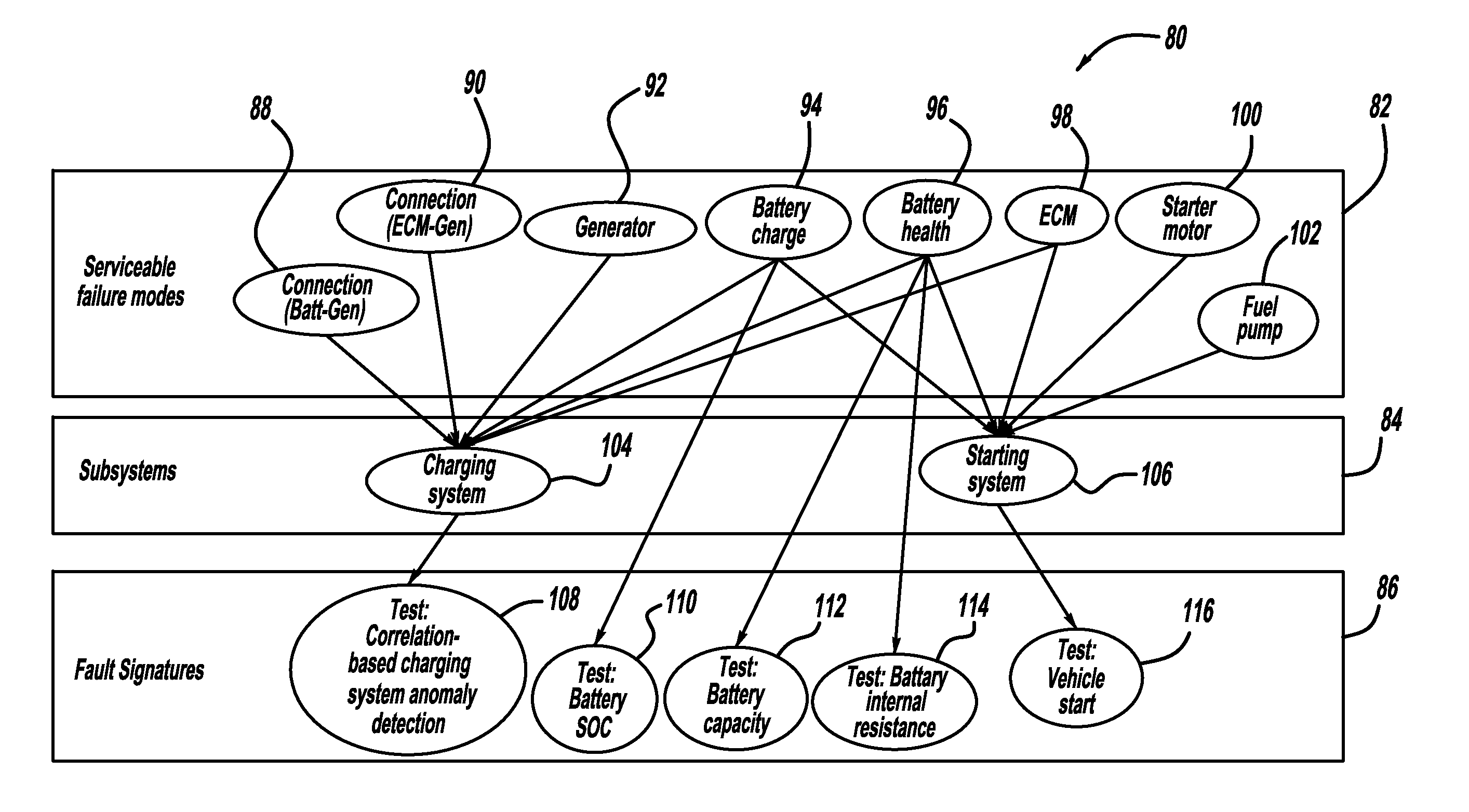
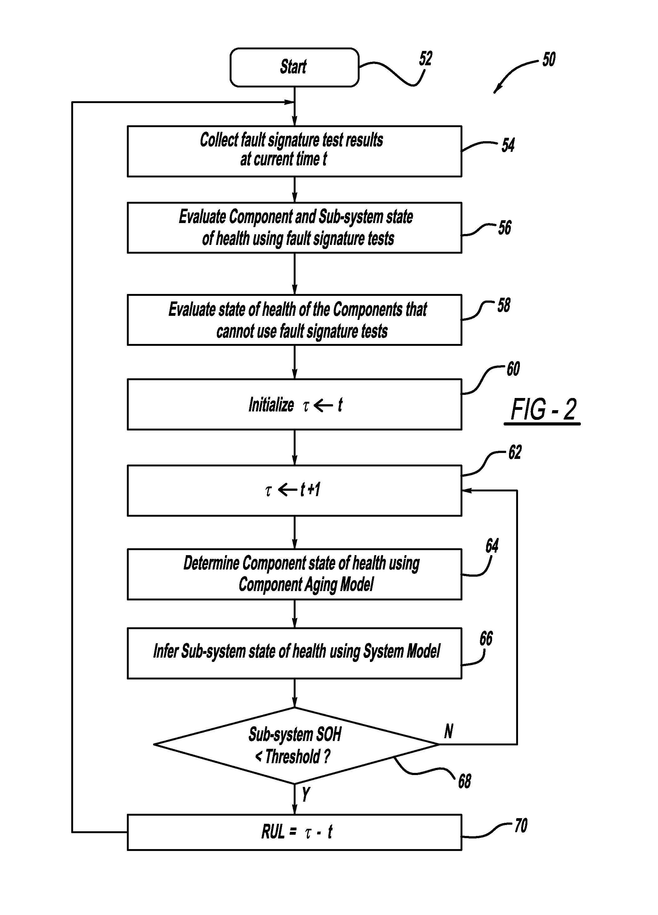
[0008]In accordance with the teachings of the present invention, a system and method are disclosed for providing component and sub-system state of health prognosis in a complex system using fault models and component aging models. The method includes collecting fault signature test results, determining a current state of health value for a sub-system using the fault signature test results and determining current state of health values for a plurality of components in the sub-system using the fault signature test results. The method also determines current state of health values for components in the system that cannot use fault signature test resu...

Problems solved by technology

As with anything, these types of devices and algorithms are susceptible to errors, failures and faults that affect the operation of the vehicle.
When such errors and faults occur, often the affected device or component will issue a fault code, such as diagnostic trouble code (DTC), that is received by one or more system controllers identifying the fault, or some ancillary fault with an integrated component.
However, fault modeling has heretofore not been used to provide the prognosis for the future state of health of complex systems.
As a system becomes more complex the ability to provide system health prognosis becomes more difficult, but just as necessary.
However, such aging models have not been extended to systems, especially complex systems.

Method used


Image

  • Health prognosis for complex system using fault modeling
  • Health prognosis for complex system using fault modeling
  • Health prognosis for complex system using fault modeling

Examples


Embodiment Construction

[0013]The following discussion of the embodiments of the invention directed to a system and method for providing state of health prognosis of components and sub-systems in a complex system using fault models and aging models is merely exemplary in nature, and is in no way intended to limit the invention or its applications or uses. For example, the system and method being described herein have particular application for providing state of health prognosis for complex vehicle systems. However, as will be appreciated by those skilled in the art, the system and method will have other non-vehicle applications.

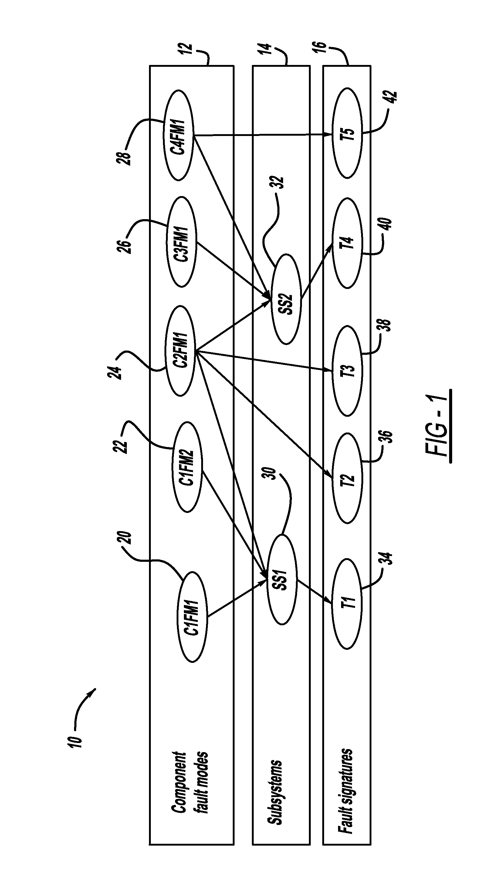
[0014]As will be discussed in detail below, the present invention employs fault models and component aging models to provide state of health prognosis for components and sub-systems in a complex system. The complex system can be any complex system suitable for fault modeling analysis, such as vehicle systems. The fault model can be any fault model suitable for the purposes describe...


PUM


Abstract

A system and method for providing component and sub-system state of health prognosis in a complex system using fault models and component aging models. The method includes determining a current state of health value for a sub-system using fault signature test results and determining current state of health values for a plurality of components in the sub-system using the fault signature test results. The method also determines current state of health values for components in the system that cannot use fault signature test results using a first probability model and the current state of health values for the plurality of components. The method determines predicted future state of health values for the components in the sub-system using component aging models and determines a predicted future state of health value for the sub-system using a second probability model and the future state of health values of the components.

Description

BACKGROUND OF THE INVENTION[0001]1. Field of the Invention[0002]This invention relates generally to a system and method for determining the future state of health of components and sub-systems in a complex system and, more particularly, to a system and method for determining the future state of health of components and sub-systems in a complex system that uses system design fault models and component aging models.[0003]2. Discussion of the Related Art[0004]Modern vehicles are complex electrical and mechanical systems that employ many components, devices, modules, sub-systems, etc. that pass electrical information between and among each other using sophisticated algorithms and data buses. As with anything, these types of devices and algorithms are susceptible to errors, failures and faults that affect the operation of the vehicle. When such errors and faults occur, often the affected device or component will issue a fault code, such as diagnostic trouble code (DTC), that is received ...

Claims


Application Information

Patent Timeline
IPC IPC(8): G06F11/07G06F7/00
CPCB60W50/0097B60W50/04Y02T10/84B60W2510/248B60W2510/244
Inventor ZHANG, YILUSALMAN, MUTASIM A.SHIN, KWANG-KEUNRAJAGOPALAN, SATISHHOWELL, MARK N.TANG, XIDONGBAE, HONG S.
Owner GM GLOBAL TECH OPERATIONS LLC
Learn More