Working Machine Maintenance Work Management System

a technology for maintenance work and working machines, applied in vehicle maintenance, instrumentation, pulse technique, etc., can solve problems such as individual discrepancies in wear sta

Active Publication Date: 2009-10-15
KOMATSU LTD
View PDF65 Cites 37 Cited by
  • Summary
  • Abstract
  • Description
  • Claims
  • Application Information

AI Technical Summary

Benefits of technology

[0014]Still further, said first service life prediction unit: for a working machine, among said plurality of working machines, which is equipped with a state detection device which detects the state of said working machine, may predict said first service life by acquiring said first parameter from data transmitted from said state detection device; and for a working machine, among said plurality of working machines, which is not equipped with such a state detection device, may predict said first service life by acquiring said fir

Problems solved by technology

However there are individual discrepancies in wear state due to, for example, the field environment in which the

Method used


Image

  • Working Machine Maintenance Work Management System
  • Working Machine Maintenance Work Management System
  • Working Machine Maintenance Work Management System

Examples


embodiment 1

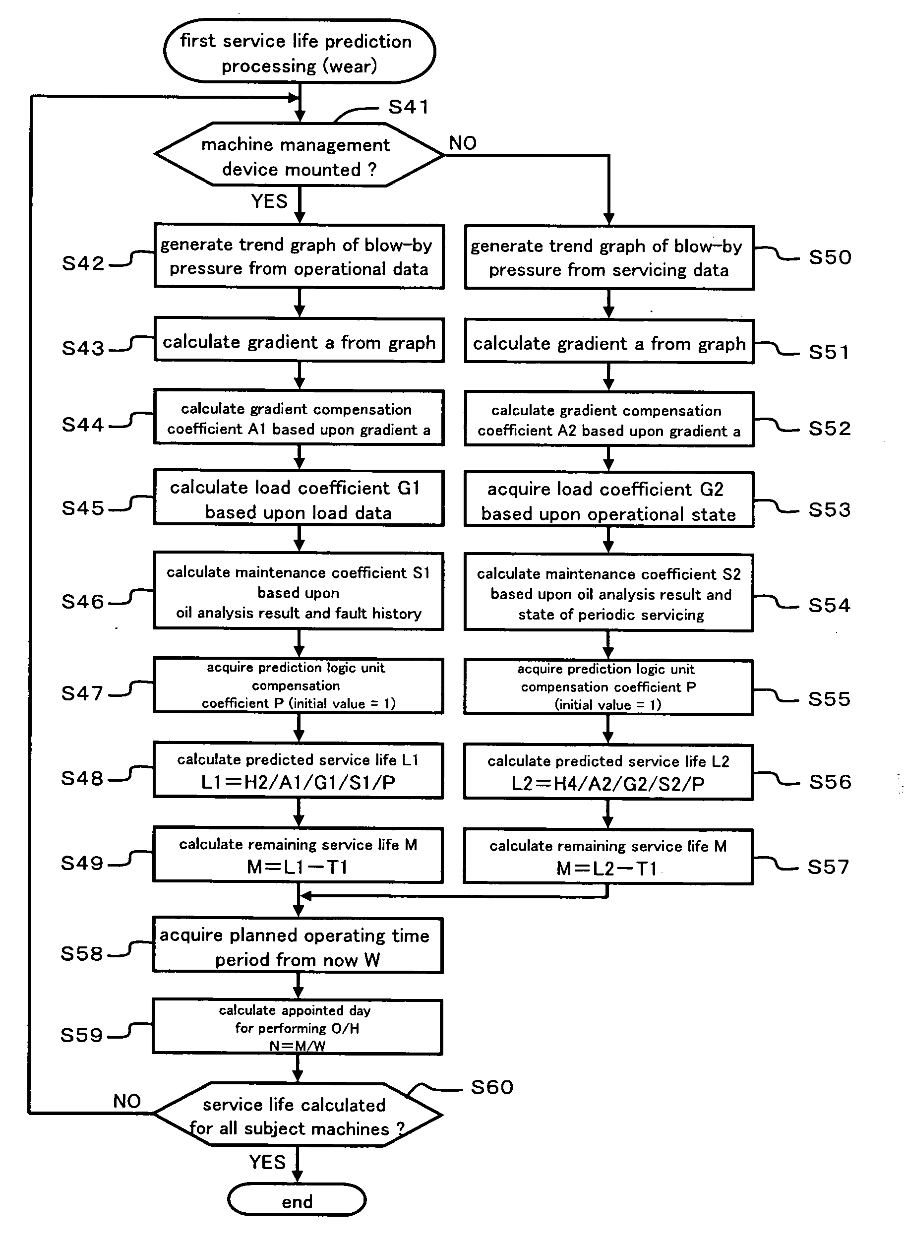
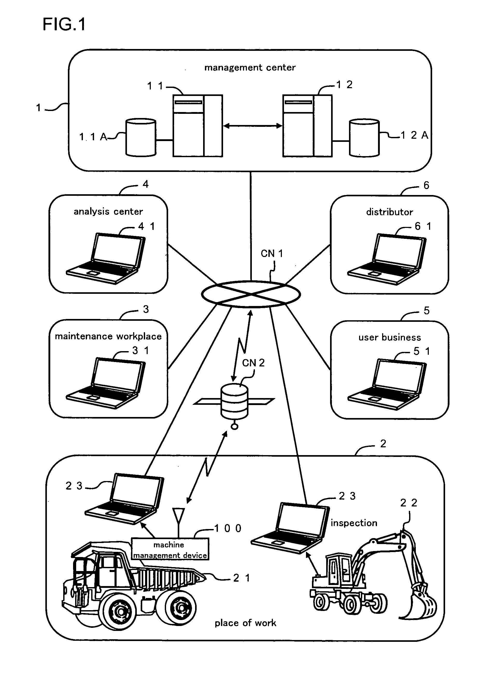
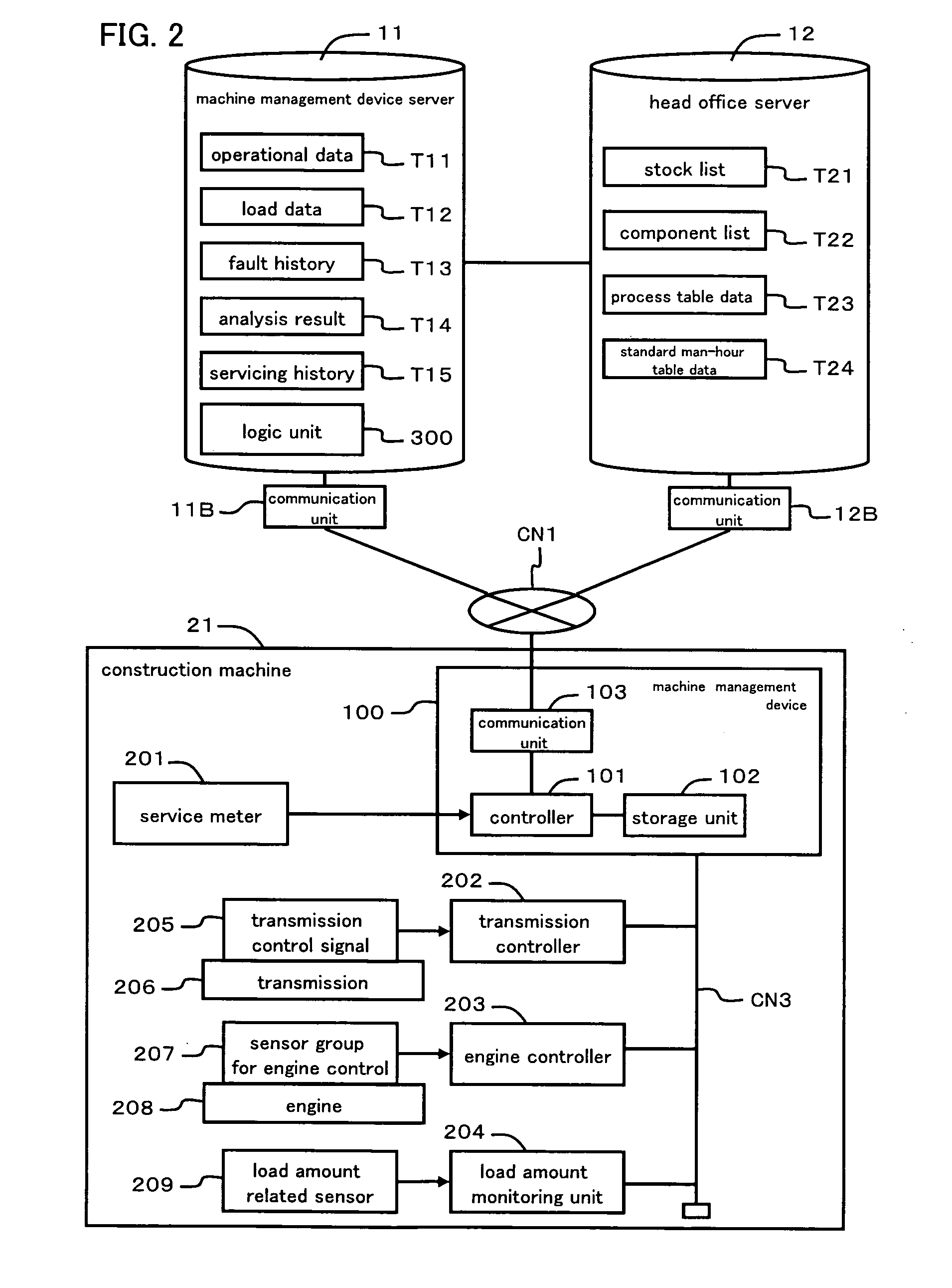
[0050]FIG. 2 is a block diagram showing examples of the structures of the management center 1 and of the construction machine 21 in more detail. The machine management device server 11 can be connected to the communication network CN1 via a communication unit 11B, and collects information of various types from the place of work 2, the maintenance workplace 3, and the analysis center 4. For example, each of operational data T11, load data T12, fault history management data T13, analysis result data T14, servicing history data T15 and so on may be accumulated in the machine management device server 11. Moreover, the machine management device server 11 comprises a logic unit 300 for predicting respective service lives for the components, based upon prediction algorithms of a plurality of types. This logic unit 300 and the various types of data T11 and so on can be used from the computer terminal for maintenance 23, the distributor terminal 61, and so on.

[0051]The head office server 12 ...


PUM


Abstract

A first service life prediction unit 311 predicts the service lives of main components, such as an engine, based upon their actual wear states. A second service life prediction unit 312 predicts the service lives of the same components, based upon their cumulative load amounts. An order setting unit 320 selects the shorter predicted service lives and sets a priority order for overhaul based thereon. An overhaul schedule table generation unit 330 creates a schedule table D1 based upon this priority order. The contents of this schedule table D1 are corrected, if necessary, by a correction unit 341. A plan creation unit 350 creates an overhaul implementation plan document D2 and the like, based upon the corrected schedule table D1a. The result of the overhaul task and the present states of components are tested, and these test results are reflected by the service life prediction units 311 and 312.

Description

TECHNICAL FIELD[0001]The present invention relates to a working machine maintenance work management system for construction machinery or the like.BACKGROUND ART[0002]A system has been suggested (in Patent Document #1) which collects information related to the working time period of a construction machine via wireless communication, and which urges the user to perform maintenance of a component whose maintenance time has arrived, if the cumulative working time period has arrived at a time which has been determined in advance by a maintenance plan. With the technique described in this document, whether or not to maintain each component is determined according to the cumulative working time period of the construction machine.[0003]However there are individual discrepancies in wear state due to, for example, the field environment in which the construction machine is used, the nature of actuation by the operator, the relative weight of the load, and so on. Accordingly, simply determining...

Claims


Application Information

Patent Timeline
IPC IPC(8): G06Q10/00G06Q50/00G06N7/02B60S5/00E02F9/20G06Q10/04G06Q50/10
CPCE02F9/20E02F9/26G06Q10/06G06Q50/04G06Q10/087G06Q10/20G06Q10/06314Y02P90/30
Inventor MIWA, HIROBUMITANINAGA, TADASHIHORI, KOUTAROUICHIKAWA, ICHIO
Owner KOMATSU LTD
Why Eureka
Try Eureka