Computer system, and backup method and program for computer system

a computer system and backup method technology, applied in the field of configuration management of storage systems, can solve the problems of reducing storage performance, high-speed medium cost, and reducing the capacity to be used,

Inactive Publication Date: 2011-08-18
HITACHI LTD
View PDF6 Cites 81 Cited by
  • Summary
  • Abstract
  • Description
  • Claims
  • Application Information

AI Technical Summary

Benefits of technology

[0010]A backup can be completed within the BW by using a plurality of types of media with different performance.

Problems solved by technology

This is because, if a backup is performed during the task, the load will be imposed on the PVOL, thereby degrading the storage performance.
Also, U.S. Pat. No. 7,613,945 does not consider copying of data between virtual volumes to which a plurality of types of media are allocated.
However, the high-speed medium is expensive, and there is a demand for reduction of the capacity to be used.

Method used


Image

  • Computer system, and backup method and program for computer system
  • Computer system, and backup method and program for computer system
  • Computer system, and backup method and program for computer system

Examples


first embodiment

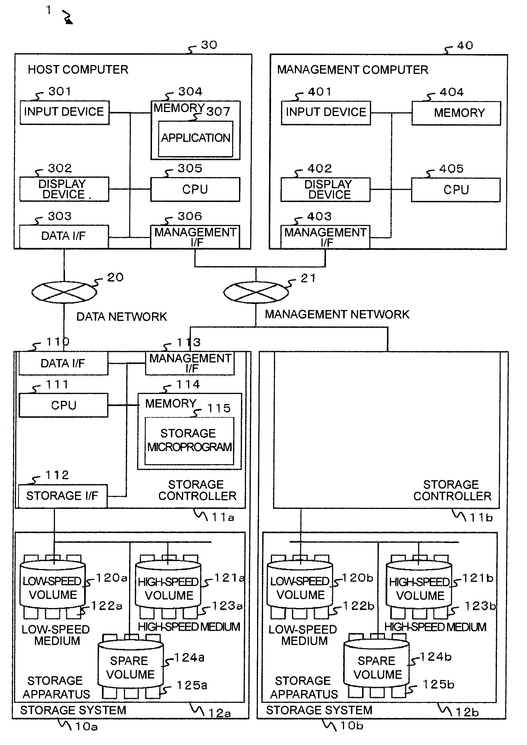
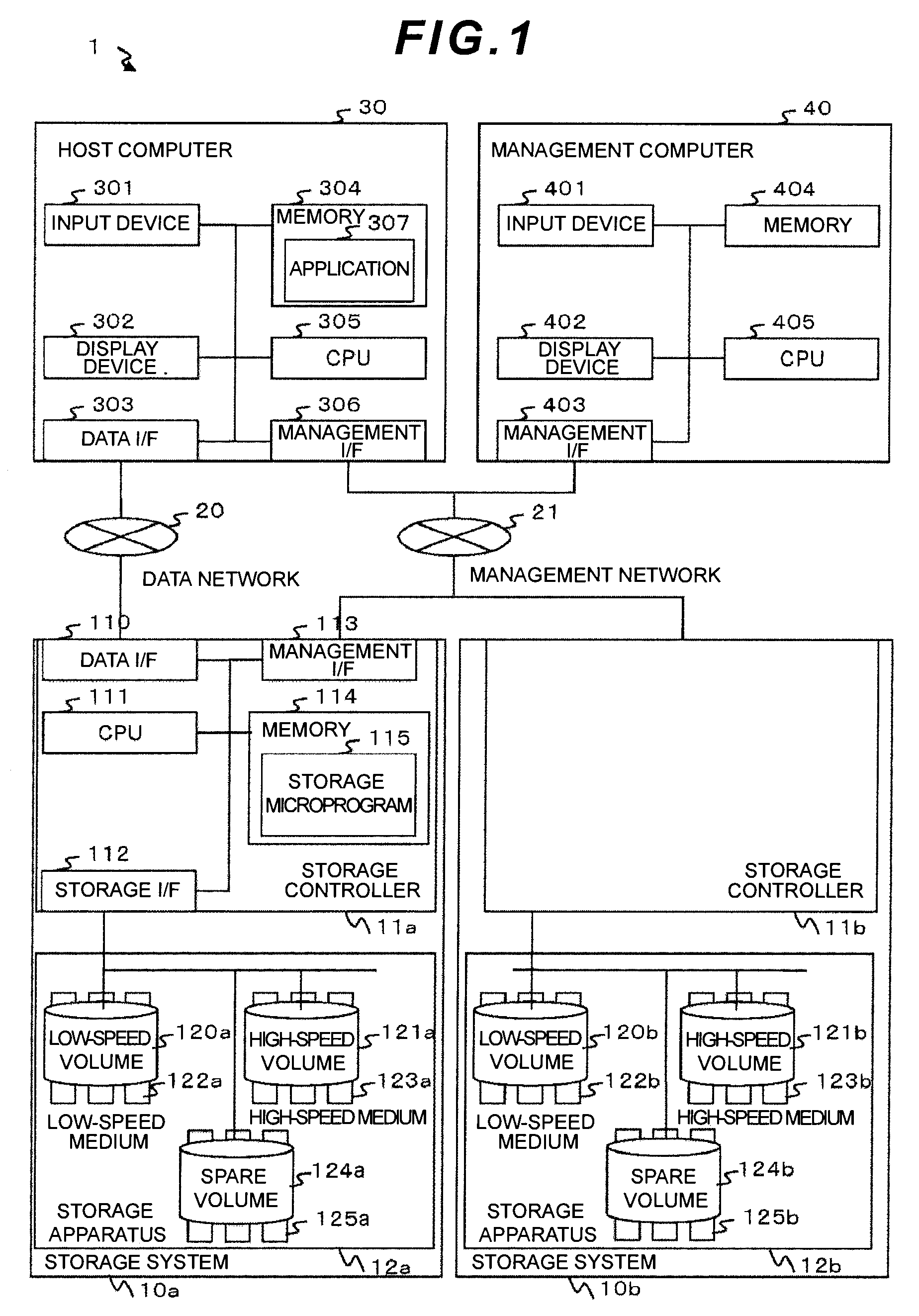
[0032]Firstly, the first embodiment of the present invention will be explained with reference to FIG. 1. FIG. 1 is a block diagram showing the configuration of a computer system 1 according to the first embodiment of the invention.

[0033]As shown in FIG. 1, the computer system 1 according to this embodiment is equipped with storage systems 10, a host computer 30, a management computer 40, a data network 20, and a management network 21. The storage systems 10 and the host computer 30 are connected to each other through their respective data interfaces (a data I / F 110 for the storage system 10 and a data I / F 303 for the host computer 30) via the data network 20. In this embodiment, the data network 20 is a SAN (Storage Area Network). However, the data network 20 may be an IP (Internet Protocol) network or other types of data communication networks. The storage systems 10, the host computer 30, and the management computer 40 are connected to each other through their respective managemen...

second embodiment

[0100]Next, the second embodiment will be explained.

[0101]The difference between this embodiment and the first embodiment is that copying of differential data is controlled on a block basis in this embodiment. The difference from the first embodiment will be explained below with regard to differential data copy processing.

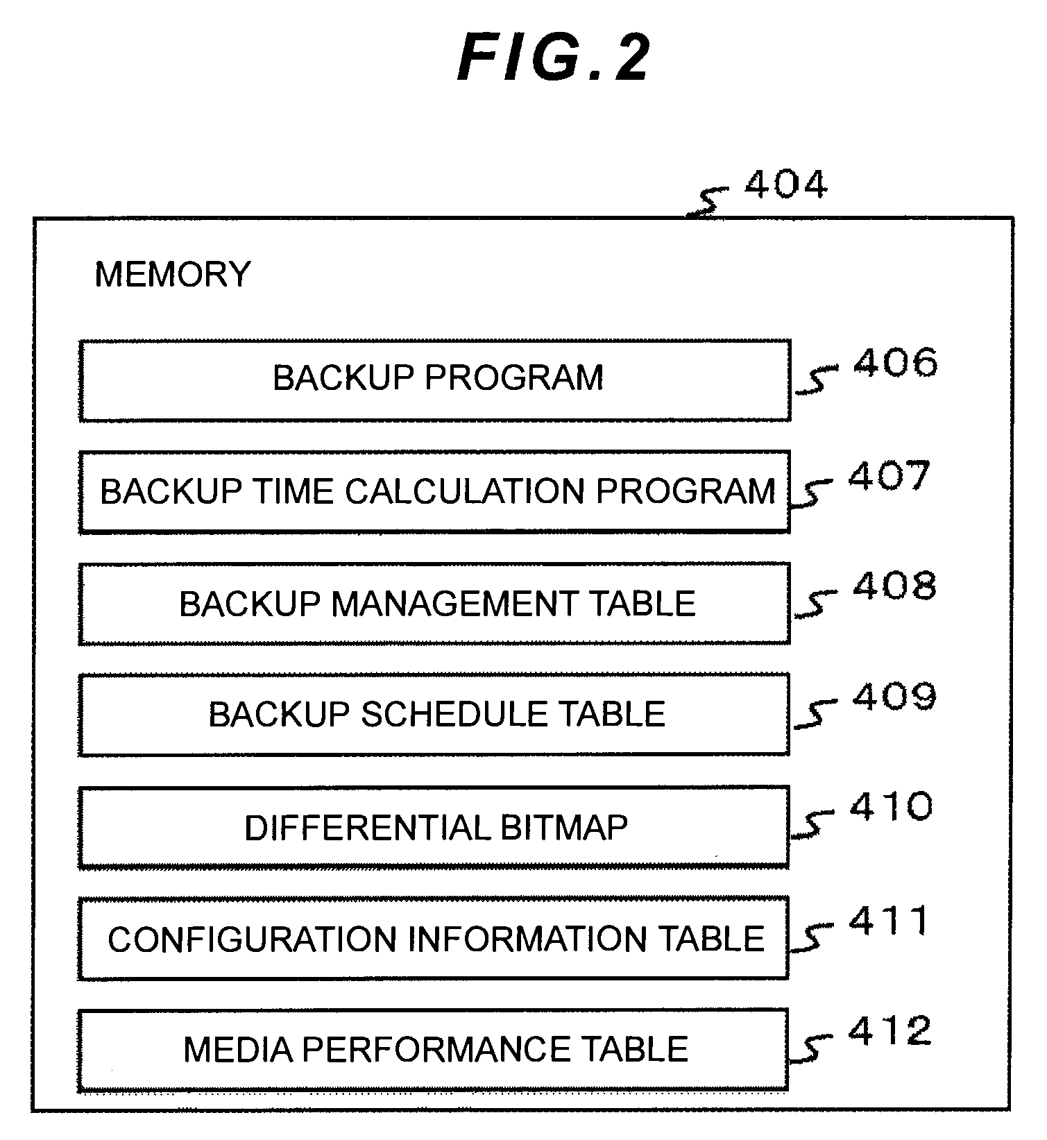
[0102]The configuration of the computer system 1 and the information stored in the memory 404 for the management computer 40 are the same as those in the first embodiment. The page ID 4115 and the capacity 4116 in the configuration information table 411 may be omitted.

[0103]Backup processing according to this embodiment will be explained below with reference to FIG. 13.

[0104]In this embodiment, the PVOL and the SVOL may not be virtual volumes. FIG. 13 illustrates that the SVOL is composed of a medium not included in a cache pool.

[0105]In the environment shown in FIG. 13, data is backed up from the PVOL to the SVOL via the cache pool. The cache pool is a pool in whi...

third embodiment

[0117]Next, the third embodiment of the present invention will be explained.

[0118]The difference between this embodiment and the first and second embodiments is that this embodiment is configured to have one storage system in the computer system according to the first and second embodiments. The following explanation will be mainly focused on the difference between the configuration of this embodiment and the configuration shown in FIG. 1 and this embodiment will describe the case in which this invention is applied to the environment where the number of storage systems is set to one.

[0119]FIG. 15 shows an example of the system configuration of a computer system 2 according to this embodiment. As shown in FIG. 14 like the computer system shown in FIG. 1, the computer system 2 according to this embodiment is constituted from a storage system 10, a host computer 30, and a management computer 40. The storage system 10, the host computer 30, and the management computer 40 are configured ...


PUM


Abstract

A backup is completed within a backup window designated by a user.
When copying data in a first storage area, which is a backup target, to a second storage area, the capacity of a medium serving as a third storage area which is sufficient to complete a backup within the backup window, is calculated based on information about a differential bitmap describing an area in the second storage area to which the relevant data is copied from the first storage area, configuration information about a storage system where the storage areas are stored, and performance information about media constituting the storage areas; and differential data is copied using the second storage area and the third storage area; and the data written to the third storage area is copied to the second storage area.

Description

CROSS-REFERENCES TO RELATED APPLICATIONS[0001]This application relates to and claims priority from Japanese Patent Application No. 2010-031940, filed on Feb. 17, 2010, the entire disclosure of which is incorporated herein by reference.BACKGROUND[0002]1. Field of the Invention[0003]The invention relates generally to configuration management of a storage system. Particularly, the invention relates to management of storage areas at the time of backups.[0004]2. Description of Related Art[0005]Companies back up data as a means of precaution against failures of storage apparatuses, data destruction by computer viruses, and data loss due to users' incorrect operation. One of backup techniques is a method of using a storage copy function capable of curbing the influence on a host computer on which an application operates. When performing a backup, data written to a storage area of a storage apparatus which stores data used by the application (primary volume; hereinafter referred to as “PVOL...

Claims


Application Information

Patent Timeline
Patent Type & Authority Applications(United States)
IPC IPC(8): G06F12/16
CPCG06F11/1451G06F11/1458G06F11/1461G06F11/1456
Inventor KONO, MISAKOMAKI, NOBUHIROEMARU, HIRONORIHARA, JUNICHI
Owner HITACHI LTD
Why Eureka
Try Eureka