
Crosscut grain sampler

a sampler and cross-cut technology, applied in the field of cross-cut grain samplers, can solve the problems of changing the price of the buyer, affecting the quality of the grain sampler, and affecting the quality of the sampler,

Inactive Publication Date: 2011-08-25
WEST CENT ROAD & RAIL
View PDF4 Cites 3 Cited by
  • Summary
  • Abstract
  • Description
  • Claims
  • Application Information

AI Technical Summary

Benefits of technology

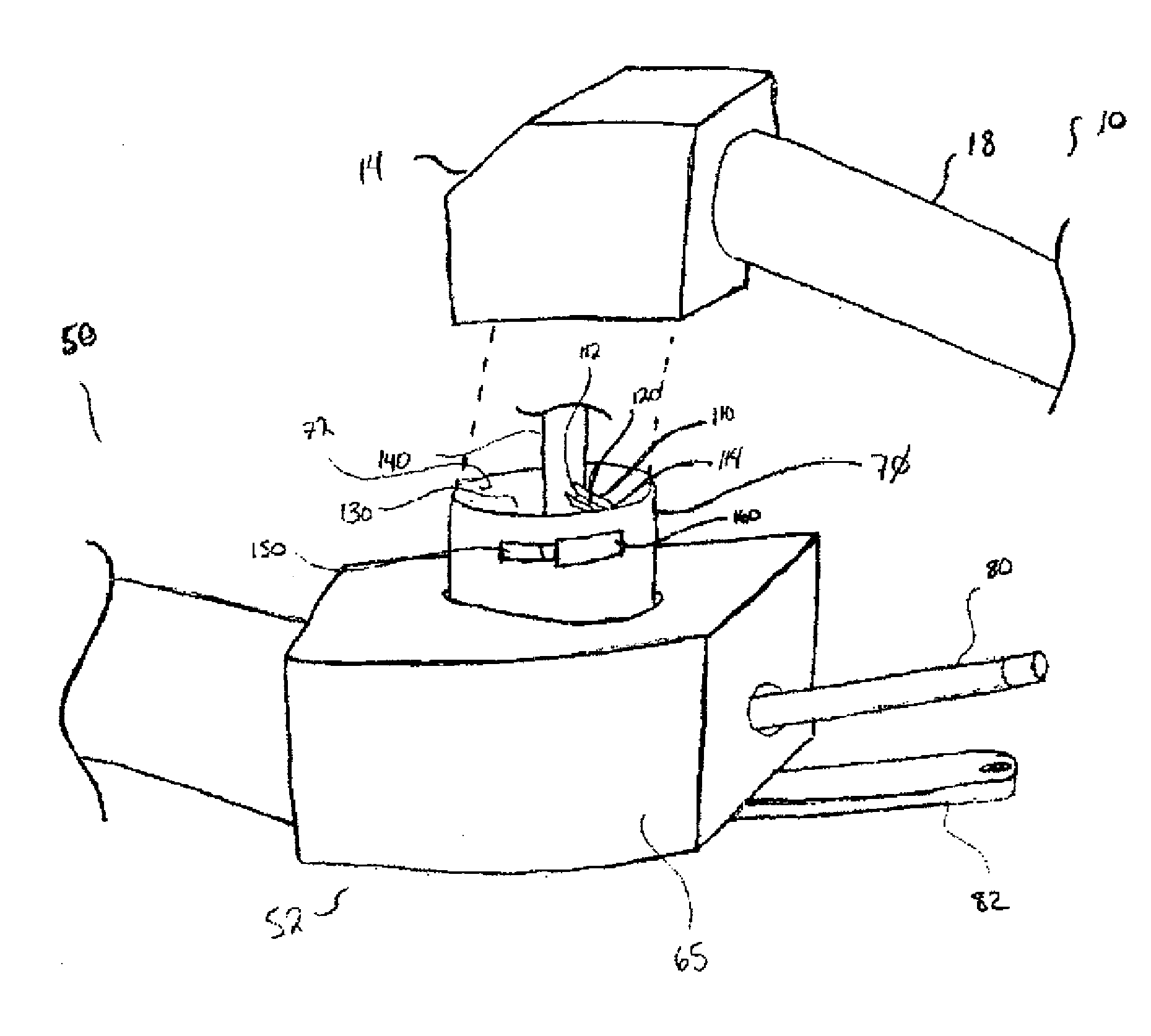
[0014]By placing the sampling device in the connecting section between a first auger section and second auger section in a swing auger, an operator can easily access the aperture used to obtain a sample of particulate matter. The connecting section on a swing auger is typically easily reachable by an operator standing on the ground beside the connecting section without requiring the operator to have to climb a ladder or be lifted up to the device. Rather, the operator can usually walk over to the aperture in the connecting section and obtain a sample. Additionally, by placing the sampling device in the connecting section of the auger system, it is placed in proximity to the power take-off connection of the auger system allowing the rotating member to be connected to the drive line of the auger system and driven by the power take-off.

Problems solved by technology

However, if the load of grain that is eventually delivered by the farmer to the buyer does not match the quality of the sample that was provided, which the buyer used to determine the price estimate, complications for the farmer arise.
This could mean a change in the price the buyer pays for the load, or if the quality of the load varies enough from the sample, the buyer may refuse to take delivery of the load of grain, requiring the farmer to take the load of grain back to the farm.
In some instances, delivery distances can be quite far and it can be quite costly to the farmer to have the grain returned back to the farm after paying the cost of having the grain delivered in the first place.
Additionally, food safety issues and problems relating to genetically engineered crops have increased the need for a fairly accurate grain sample to be taken from a load of grain, with many purchasers requiring these fairly accurate samples of a load of grain.
However, the device is positioned in its own casing beneath a discharge spout of the auger, which requires the device to be positioned quite high off the ground, preventing an operator from easily obtaining a grain sample with the device.
Finally, the placement of this disclosed device requires it to be driven by impeller blades attached beneath the device increasing the complexity of the device and requiring the device's performance to be based on getting adequate flow rates of grain through the casing in order to properly drive the sampling device.

Method used


Image

  • Crosscut grain sampler
  • Crosscut grain sampler
  • Crosscut grain sampler

Examples


Embodiment Construction

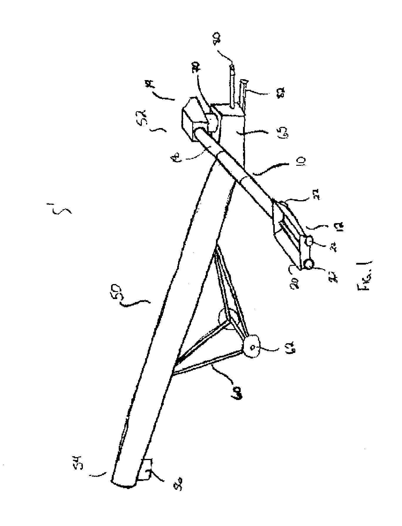
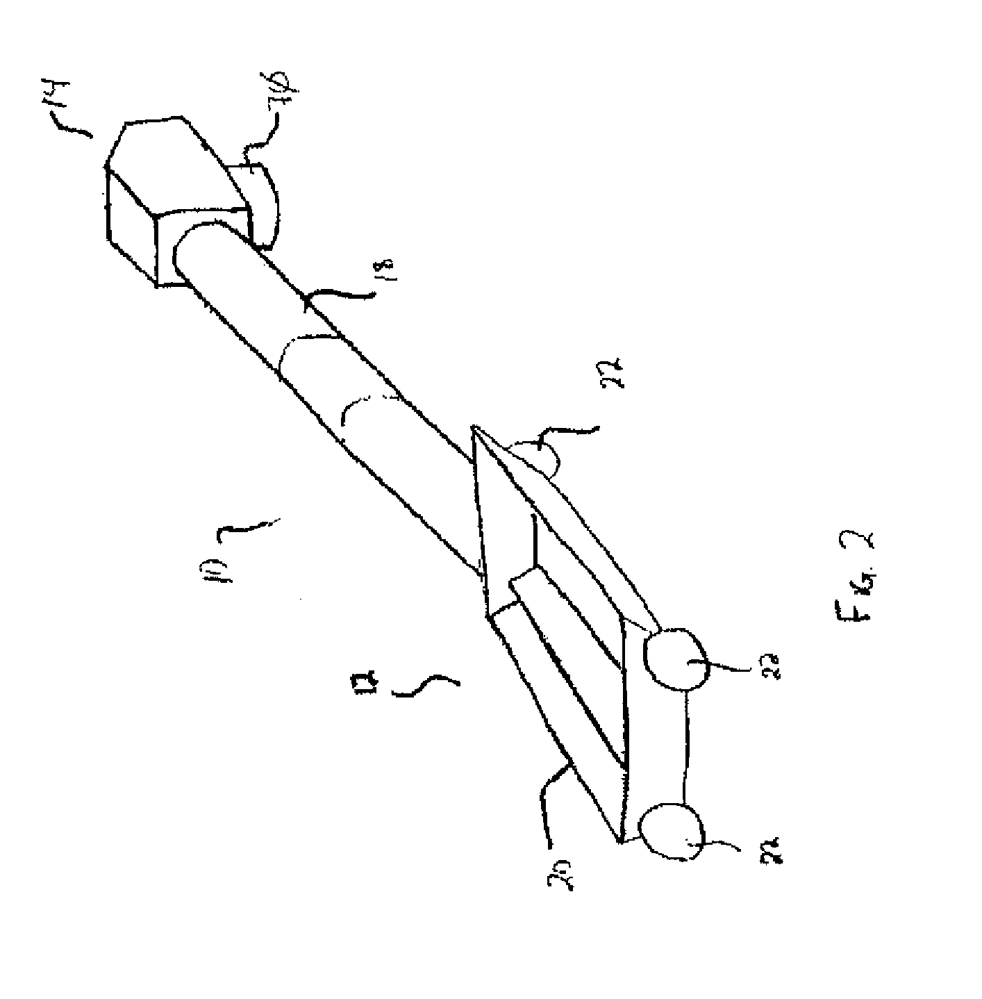
[0020]FIG. 1 illustrates an auger system 1. The auger system 1 has a first auger section 10 and a second auger section 50. The first auger section 10 is a swing auger and is pivotally connected to the second auger section 50 which is a main auger. The first auger section 10 is used to load particulate material, such as grain, from a low point, such as under a grain truck and lift it to be loaded into an intake end 52 of the second auger section 50. The second auger section 50 is typically much longer than the first auger section 10, with the first auger section 10 typically being just long enough to lift particulate material loaded in the intake end 12 of the first auger section 10 to the intake end 52 of the second auger section 50 and the second auger section 50 providing the majority of the lift provided by the auger system 1. The second auger section 50 lifts the particulate material along its length, where it is then discharged from a discharge end 54 of the second auger sectio...


PUM


Abstract

A sampling device having an elongate member positioned in the connecting section of a swing type auger is provided. The member has a channel facing into a flow of particulate matter passing through the connecting section and an open end. The member is attached to a rotating shaft. When the auger system is in operation and particulate matter is flowing through the connecting section, the arm rotates perpendicularly through the flow of particulate material and a portion of this particulate material is collected in the channel of the rotating member. The rotation of the member causes the collected particulate material to move along the length of the rotating member until it is thrown out the open end of the member, where a sample can be collected through an aperture in the side of the connecting section.

Description

[0001]This invention is in the field of particulate material sampling devices and more particularly is directed to a particulate material sampling device incorporated into a swing auger.BACKGROUND[0002]A definite need exists for a low cost grain sampler that can be used on the farm and provide a good representative sample of the grain being sampled. Typically, when a farmer agrees to deliver a load of grain to a buyer, a farmer will first deliver a sample of the grain to the buyer, so that the buyer and the farmer can determine a price for the load of grain. The buyer will then provide the farmer with a price estimate for the load based on the sample of grain taken by the farmer. However, if the load of grain that is eventually delivered by the farmer to the buyer does not match the quality of the sample that was provided, which the buyer used to determine the price estimate, complications for the farmer arise. This could mean a change in the price the buyer pays for the load, or if...

Claims


Application Information

Patent Timeline
IPC IPC(8): G01N1/20
CPCA01D75/02G01N1/04A01D87/00
Inventor BYRNES, GLENNWOODS, BILL
Owner WEST CENT ROAD & RAIL
Learn More