
Device and method to develop potential images generated on an intermediate image carrier in an electrographic printing or copying device

a technology of electrographic printing or copying device and image carrier, which is applied in the direction of optics, instruments, electrographic/magnetography, etc., can solve the problems of limited toner application per surface element, limited transfer of toner particles to the raster roller, and insufficient ink flow of developer fluid in the chamber blade, etc., to achieve substantially uniform inking of potential images, high printing speed, and stable

Inactive Publication Date: 2011-08-25
OCE PRINTING SYST
View PDF8 Cites 17 Cited by
  • Summary
  • Abstract
  • Description
  • Claims
  • Application Information

AI Technical Summary

Benefits of technology

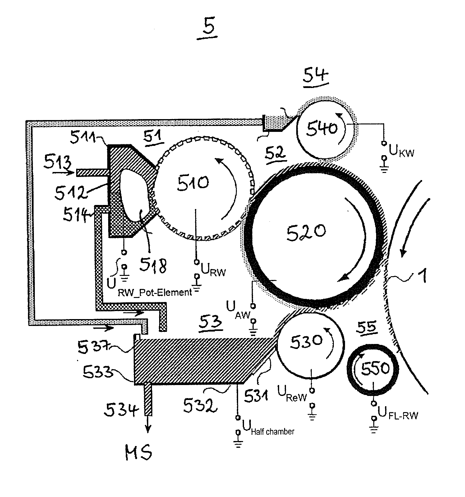
[0007]It is an object to specify a device and a method with which a stable, substantially uniformly high inking of the potential images on an intermediate image carrier can be achieved in electrostatic printing methods. A high printing speed should thereby be possible.

Problems solved by technology

One disadvantage of the chamber blades known from these is that the flow of the developer fluid in the chamber blade is not specifically directed.
In addition to this, the filling of the cups of the raster roller takes place without potential assistance, such that the transfer of the toner particles to the raster roller is limited.
The achievable toner application per surface element is thereby limited, and therefore the inking region or the speed of the transfer of the developer fluid onto the raster roller (and therefore the achievable process speed given constant inking).
However, an elastic coating of the applicator roller that is required for the nip formation at the intermediate image carrier is rapidly worn by the blade.
In contrast to this, if the contact pressure of the blade is too weak a poor cleaning efficiency is accepted, which leads to memory effects given high print utilization (degree of areal coverage of the print image) since not every point of the applicator roller has the same toner quantity / area after a cycle.

Method used


Image

  • Device and method to develop potential images generated on an intermediate image carrier in an electrographic printing or copying device
  • Device and method to develop potential images generated on an intermediate image carrier in an electrographic printing or copying device
  • Device and method to develop potential images generated on an intermediate image carrier in an electrographic printing or copying device

Examples


Embodiment Construction

[0011]For the purposes of promoting an understanding of the principles of the invention, reference will now be made to a preferred embodiment / best mode illustrated in the drawings and specific language will be used to describe the same. It will nevertheless be understood that no limitation of the scope of the invention is thereby intended, and such alterations and further modifications in the illustrated method and such further applications of the principles of the invention as illustrated as would normally occur to one skilled in the art to which the invention relates are included.

[0012]Some objects which are achieved with one preferred embodiment are:[0013]a stable, uniform and high level of inking of the potential images;[0014]a stable inking for high print speed;[0015]a high process stability (long term stability)[0016]for a large areal coverage range (0-100%);[0017]for a large process speed range (0.3 to 5 m / sec);[0018]with minimized loading of the developer fluid;[0019]a high ...


PUM


Abstract

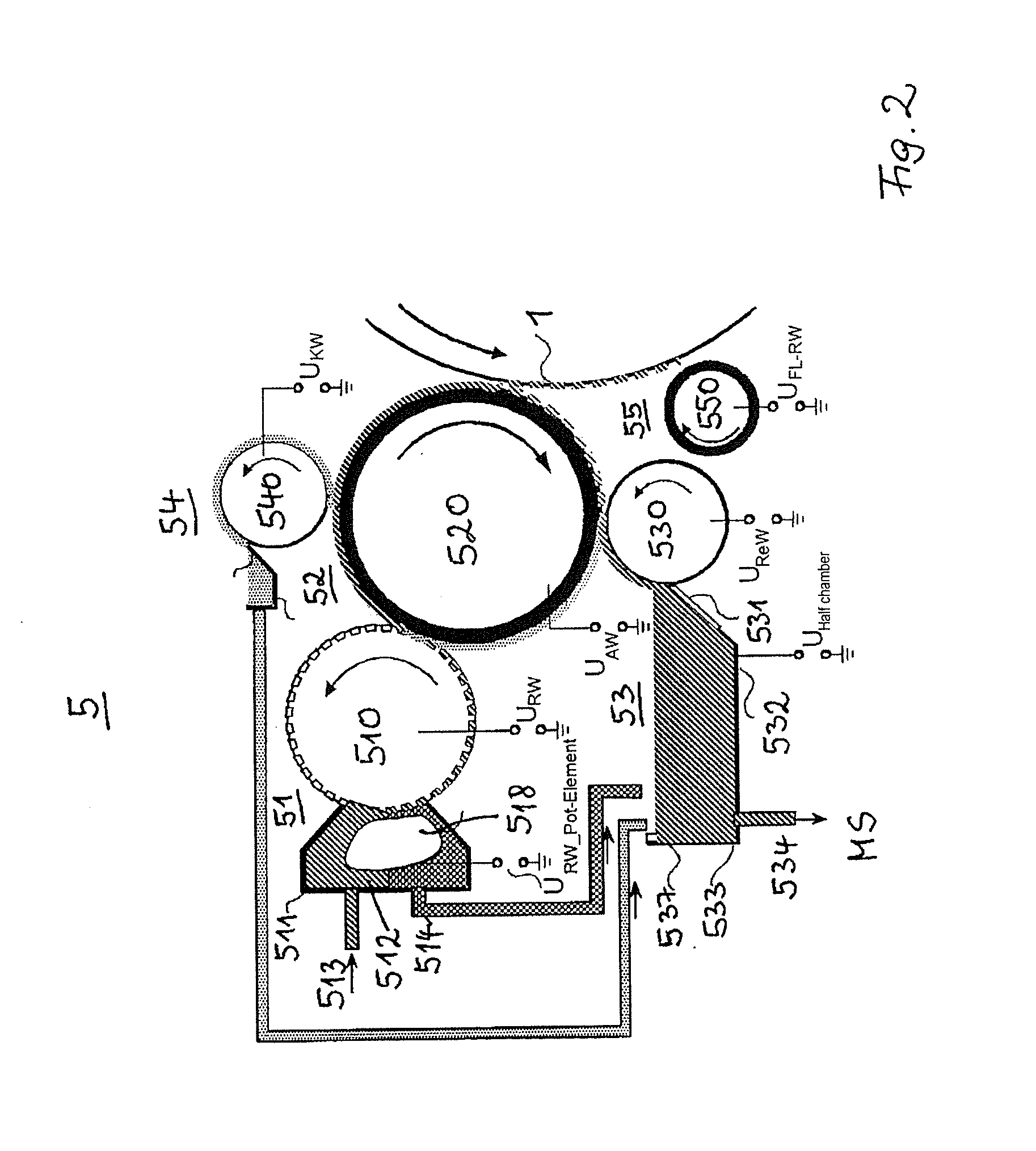
In a device or method to develop potential images of images to be printed, the potential images being generated on an intermediate image carrier using developer fluid having a charged toner and carrier fluid, developing with an applicator device the potential images, the applicator device directing the developer fluid across the intermediate image carrier. With the feed device the developer fluid is supplied to the applicator device, the feed device discharging excess developer fluid depleted of toner and that is not transferred to the applicator device. With a conditioning device the carrier fluid is taken from the applicator device and the taken up carrier fluid is discharged. With a cleaning device residual developer fluid remaining after development of the potential images is cleaned off of the applicator device and the residual developer fluid is supplied to a chamber arranged in the cleaning device. The discharge from the feed device and the discharge from the conditioning device are fed to the cleaning device chamber.

Description

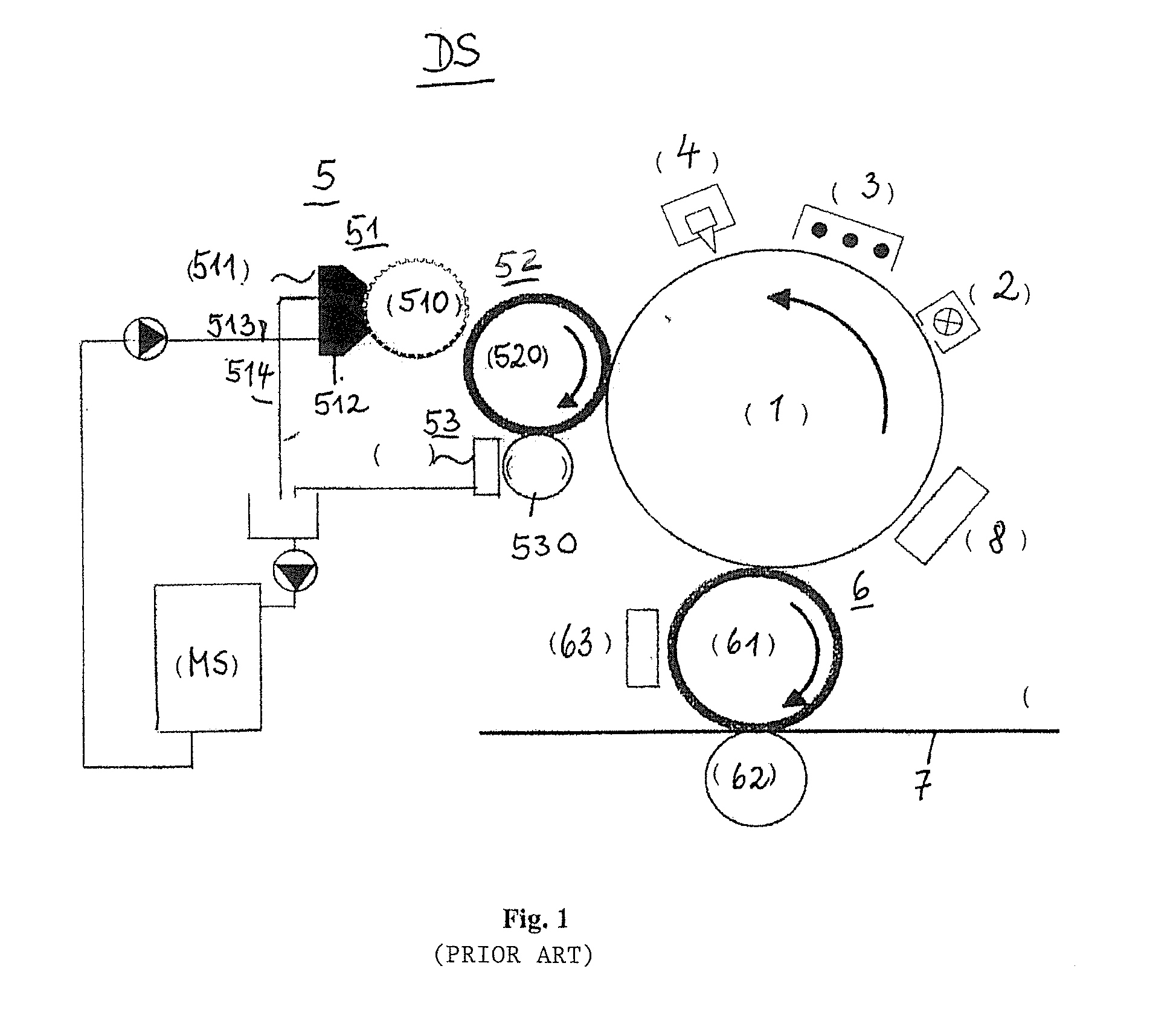
BACKGROUND OF THE INVENTION[0001]For single color or multicolor printing of a recording material (for example a single sheet or a belt-shaped recording material) made of the most varied materials, for example paper or thin plastic or metal films, it is known to generate image-dependent potential images (charge images) on an intermediate image carrier (for example a photoconductor) that correspond to the images to be printed and comprised of regions (image areas) that are to be inked and regions that are not to be inked (non-image areas). The regions of the potential images that are to be inked are made visible via toner with a developer station. The toner image is subsequently transfer-printed onto the recording material.[0002]Developer fluid containing toner and carrier fluid can thereby be used to ink the potential images. The carrier fluid thereby has a specific resistance of greater than 108 Ohm*cm. Possible carrier fluids are silicon oil and hydrocarbons, among other things.[00...

Claims


Application Information

Patent Timeline
IPC IPC(8): G03G15/10
CPCG03G15/11G03G15/104
Inventor BERG, MARTIN
Owner OCE PRINTING SYST
Learn More