
Body Parameter Sensor and Monitor Interface

Inactive Publication Date: 2011-08-25
EDWARDS LIFESCIENCES CORP
View PDF23 Cites 23 Cited by
  • Summary
  • Abstract
  • Description
  • Claims
  • Application Information

AI Technical Summary

Benefits of technology

[0011]The system may be configured to receive and dynamically store a history of physiological parameters over a predetermined period of time, as well as a wide variety of other information, such as but not limited to: patient identification, patient information such as age, gender, weight, body mass index and/or other information, device identification such as serial number, model number, lot number and/or other information, calibration data or other data pertaining to the sensor itself, scaling factors, monitored physiological parameters over a predetermined period of time (e.g. over the past 8 hours, the past 24 hours, or other time period as desired), data about a

Problems solved by technology

As a result, the use of physiological sensors and associated monitoring may increase the likelihood that a patient can be successfully treated or provided with needed emergency assistance.
However, transducers from different sources may exhibit different performance characteristics and may require specific calibration or signal processing or conditioning.
Unfortunately, the environments of the OR, ICU or CCU are ill-suited for rapid recognition and registration of disparate components of pressure monitoring systems, and safety concerns necessitate the least amount of such preparation be involved.
However, this “piggyback” connection may introduce pressure monitoring errors from delays and distortion of the signals.
Movement of a patient from one location to another also can present problems.
Removing and reinserting a sensor in the patient is generally undesirable, therefore the sensor usually remains in the patient and is then plugged into a new monitor at the new location.
Data continuity is disrupted, therefore, each time a patient is moved.

Method used


Image

  • Body Parameter Sensor and Monitor Interface
  • Body Parameter Sensor and Monitor Interface
  • Body Parameter Sensor and Monitor Interface

Examples


Embodiment Construction

[0022]Aspects of the present invention now will be described more fully with reference to the accompanying drawings, in which some but not all embodiments of the invention are shown. Indeed, the invention may be embodied in many different forms and should not be construed as limited to the embodiments set forth herein; rather, these embodiments are provided so that this disclosure will satisfy applicable legal requirements. Like numbers refer to like elements throughout.

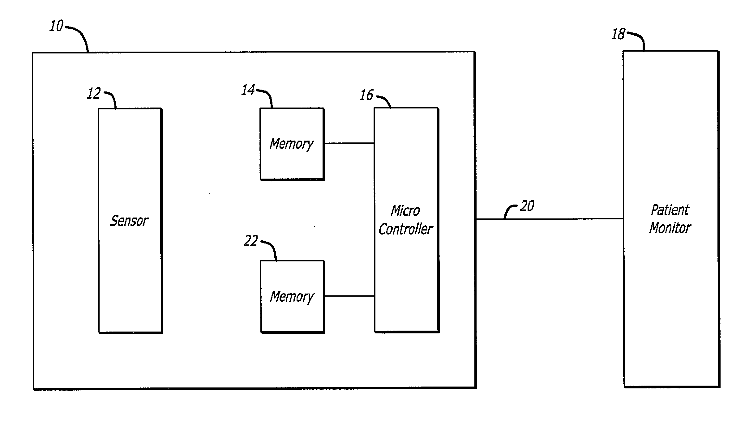
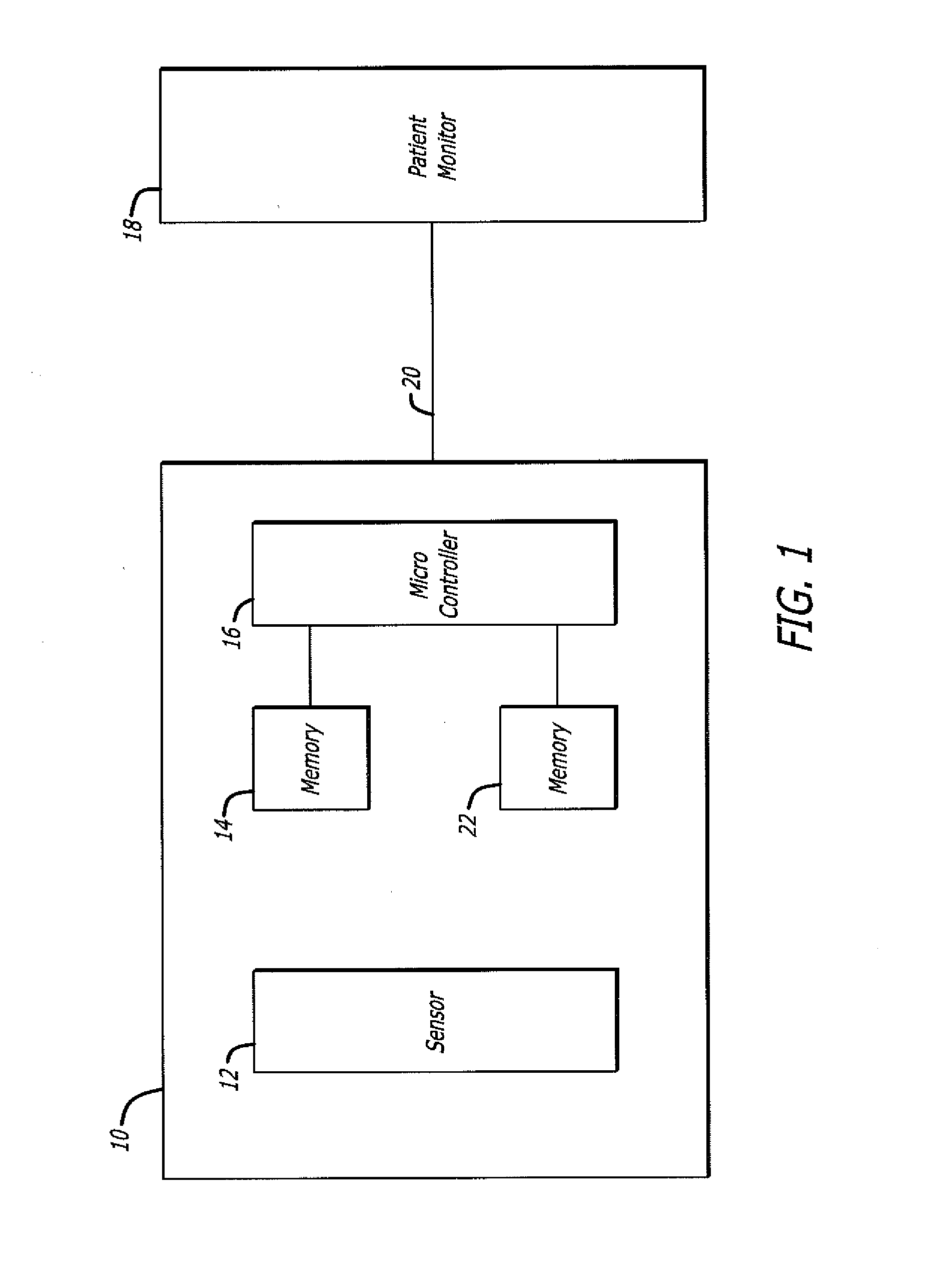
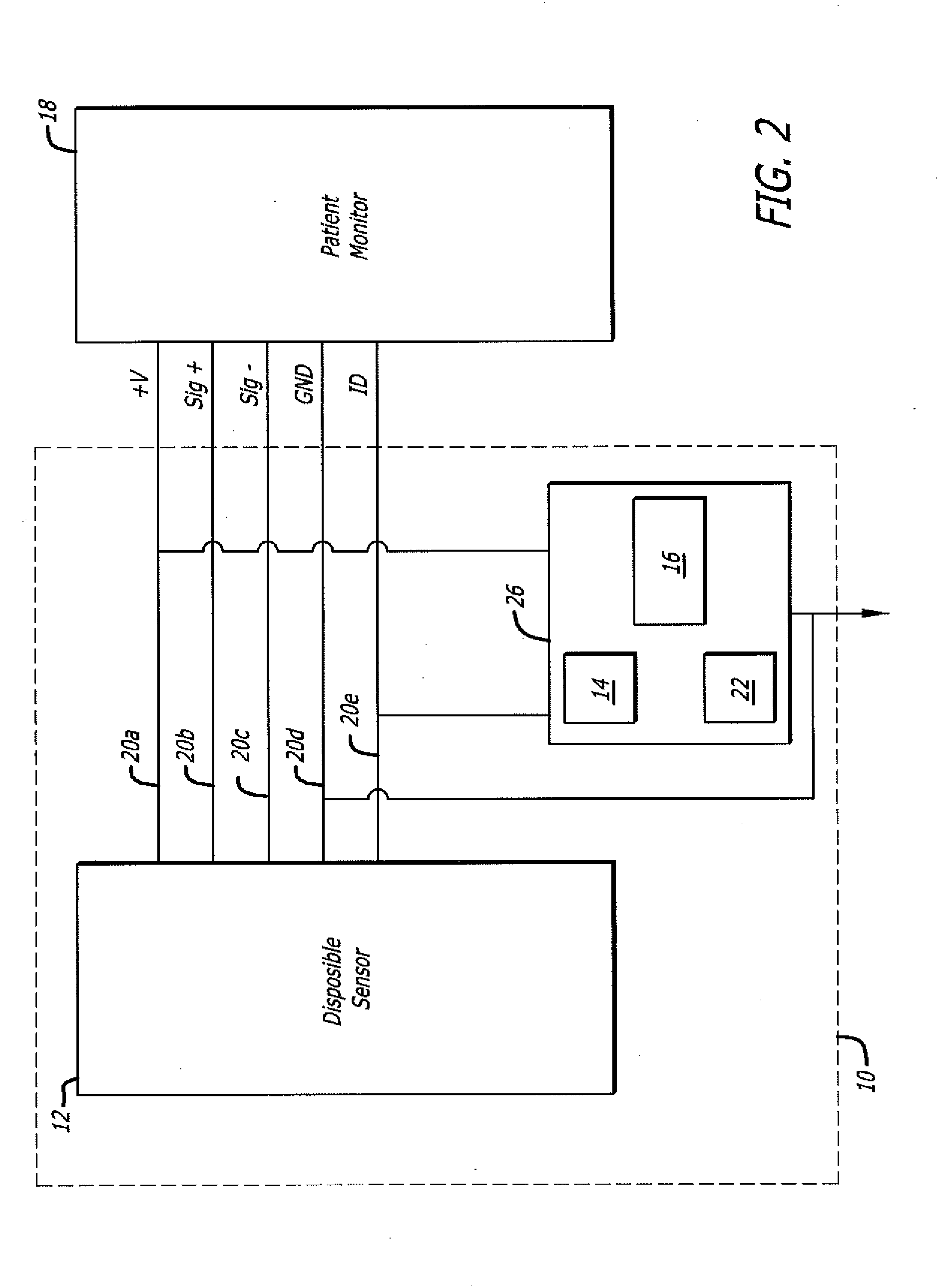
[0023]Generally, the present invention includes all, or portions of, a sensing system 10 (FIG. 1). Various embodiments or features of the invention will be presented in terms of systems that may include a number of devices, components, modules, and the like. It is to be understood and appreciated that the various systems may include additional devices, components, modules, etc. and / or may not include all of the devices, components, modules etc. discussed in connection with the figures. A combination of these approach...


PUM


Abstract

A system for sensing a physiological parameter in a human or animal, and storing a processed sensing signal at a sensor with which the sensing was performed. The system includes a physiological sensor adapted to output a sensor signal representative of a sensed physiological parameter, for processing by a remote processor. A microcontroller has memory, and is located locally to the sensor and is fixedly attached to or housed together with the sensor. An authentication algorithm is stored in the memory and the microprocessor is configured to engage in an authentication process to authenticate the sensor when queried by a remote processor. The memory is configured to receive and store data representative of a sensed physiological parameter after data from the sensor has been processed by a remote processor. The microcontroller may be configured to communicate with a remote processor over a single wire by, for example, using a single wire protocol.

Description

FIELD OF THE INVENTION[0001]The present invention relates generally to sensors of physiological parameters, such as pressure transducers and fluid monitors, and, more particularly, to disposable physiological sensors and associated patient monitor interfaces.BACKGROUND OF THE INVENTION[0002]When diagnosing and treating various bodily ailments, such as with patients suffering from shock or cardiovascular problems, medical personnel often find it desirable to measure or monitor a patient's blood pressure and / or other physiological parameters. Advantageously, by measuring or monitoring physiological parameters of these and other types of patients, medical personnel are better able to detect medical difficulties and other problems at an early stage. As a result, the use of physiological sensors and associated monitoring may increase the likelihood that a patient can be successfully treated or provided with needed emergency assistance.[0003]A variety of methods are currently used for mea...

Claims


Application Information

Patent Timeline
IPC IPC(8): A61B5/00
CPCA61B5/022A61B5/002A61B2562/08A61B2560/045
Inventor PHAN, LUONG NGOCBACKER, STEVENWILBUR, JENNIFERHIGGINS, MICHAEL
Owner EDWARDS LIFESCIENCES CORP
Learn More