Thermally operated valve

Inactive Publication Date: 2011-09-01
HAMILTON SUNDSTRAND SPACE SYST INT
View PDF20 Cites 5 Cited by
  • Summary
  • Abstract
  • Description
  • Claims
  • Application Information

AI Technical Summary

Benefits of technology

[0005]A valve has a housing including a valve seat. A valve pin is supported by a support shell. The support shell and the valve pin have distinct coefficients of thermal expansion such that when expos

Problems solved by technology

The use of an actuator requires additional components, and is somewhat expensiv

Method used


Image

  • Thermally operated valve
  • Thermally operated valve

Examples


Embodiment Construction

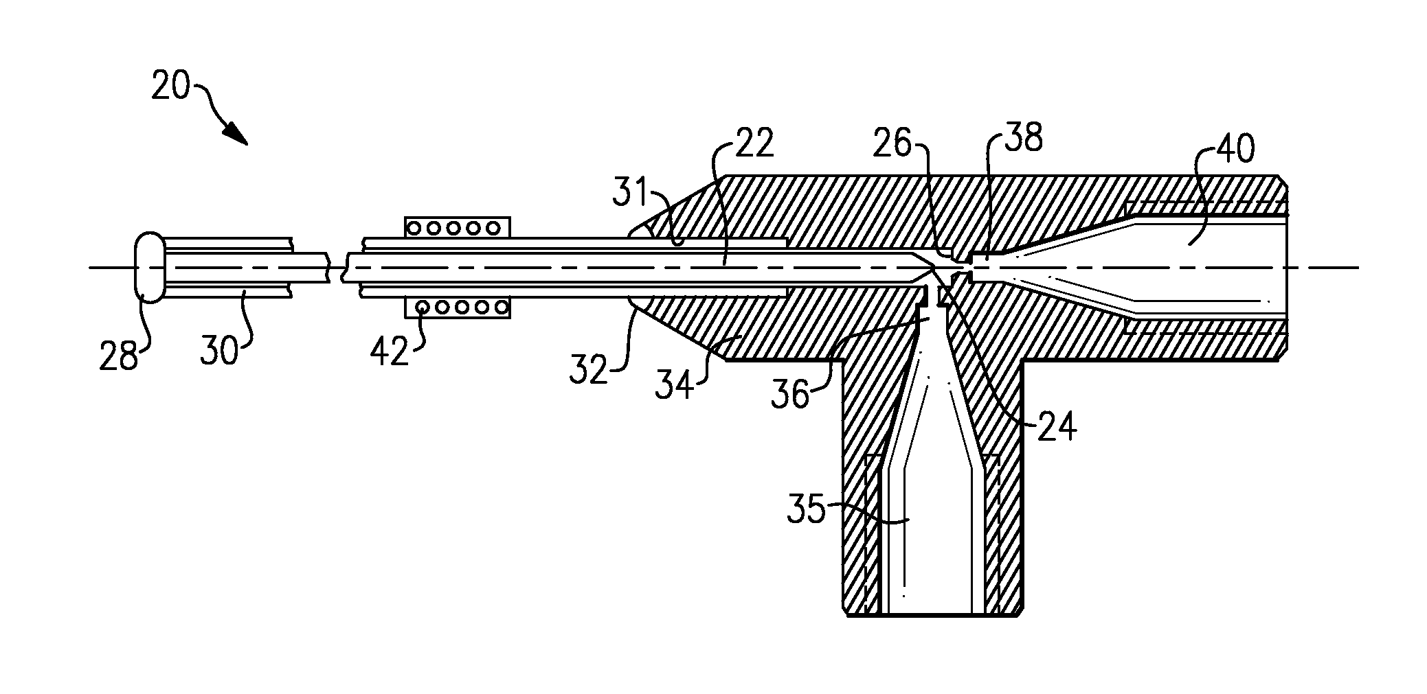
[0010]A valve 20 is shown in FIG. 1A having a valve pin 22. Valve pin 22 has a head 24 that selectively seats in a valve seat 26 to control the flow of a fluid from an upstream location 35, to a port 36, through the valve seat 26, and to a downstream port 38 in a downstream connection 40.

[0011]The valve pin 22 is coupled at 28 to a support shell 30. The support shell 30 is received within a bore 31, and coupled at 32 to the housing 34. The coupling at 28 and 32 may be performed by welding or other techniques known in the art. The support shell 30 is formed of a material having a different coefficient of thermal expansion than the valve pin 22. The difference in the coefficient of thermal expansion may be selected such that the coefficient of one of the materials will be at least twice the coefficient of the other. This will provide significant movement that can be achieved in a relatively short period of time to provide better control over the amount of a sample fluid, as an example...


PUM


Abstract

A valve has a housing including a valve seat. A valve pin is supported by a housing through a support shell. The support shell and the valve pin have distinct coefficients of thermal expansion such that when exposed to a temperature change, movement of the support shell moves differently than the pin. In this way, the valve pin can be caused to move toward and away from the valve seat to allow operation of the valve.

Description

BACKGROUND OF THE INVENTION[0001]This application relates to a valve that provides precise movement of a valve pin relative to a valve seat through the use of materials having distinct coefficients of thermal expansion.[0002]Valves are utilized in any number of applications to control the flow of fluids from one location to another. In a typical valve, a valve seat receives a valve pin, and when the valve pin is seated in the seat, fluid flow is blocked from an upstream location to a downstream location. The valve pin is moved relative to the valve seat to allow fluid flow.[0003]Typically, some actuator is provided to move the valve pin. The use of an actuator requires additional components, and is somewhat expensive. Moreover, the actuator may not provide precise movement, or adequate sealing.[0004]It has been proposed to utilize a material which expands or contracts with heating and cooling to form the valve pin. In such valves, the valve pin moves when heated to allow flow of flu...

Claims


Application Information

Patent Timeline
IPC IPC(8): F15D1/00
CPCF16K31/002F03G7/06Y10T137/7737Y10T137/0324
Inventor CHUN, RICHARD K.
Owner HAMILTON SUNDSTRAND SPACE SYST INT
Why Eureka
Try Eureka