
Mesh network remote control device

a remote control device and network technology, applied in data switching networks, testing/monitoring control systems, instruments, etc., can solve the problems of difficult dynamic management of complex routing information, difficult to determine the load on a mesh network and what resources are required, and none of these solutions solve all of the problems associated with mesh networks

Active Publication Date: 2011-09-01
III HLDG 2
View PDF5 Cites 84 Cited by
  • Summary
  • Abstract
  • Description
  • Claims
  • Application Information

AI Technical Summary

Benefits of technology

The present invention provides a mesh network remote control device that can communicate with other mesh network devices, non-mesh network devices, and even with a user's own devices through a simple display. The device can accept commands from various sources and transform them into simple display commands for easy use. This invention solves the problems associated with mesh networks and provides greater flexibility and efficiency in controlling remote devices.

Problems solved by technology

There are a number of problems associated with wired and wireless mesh networks.
One problem is that a number of independent mesh devices each make a local decision and then try to combine these decisions at a central point to generate a global decision.
Another problem is that is often difficult to determine a load on a mesh network and what resources are required to determine a desired quality of service.
Another problem is that some mesh networks are mobile networks in which it is assumed at least some of the nodes of the network are mobile units that change position over time.
The dynamic management of complex routing information is very difficult.
However, none of these solutions solve all of the problems associated with mesh networks.

Method used


Image

  • Mesh network remote control device
  • Mesh network remote control device
  • Mesh network remote control device

Examples


Embodiment Construction

Exemplary Mesh Network System

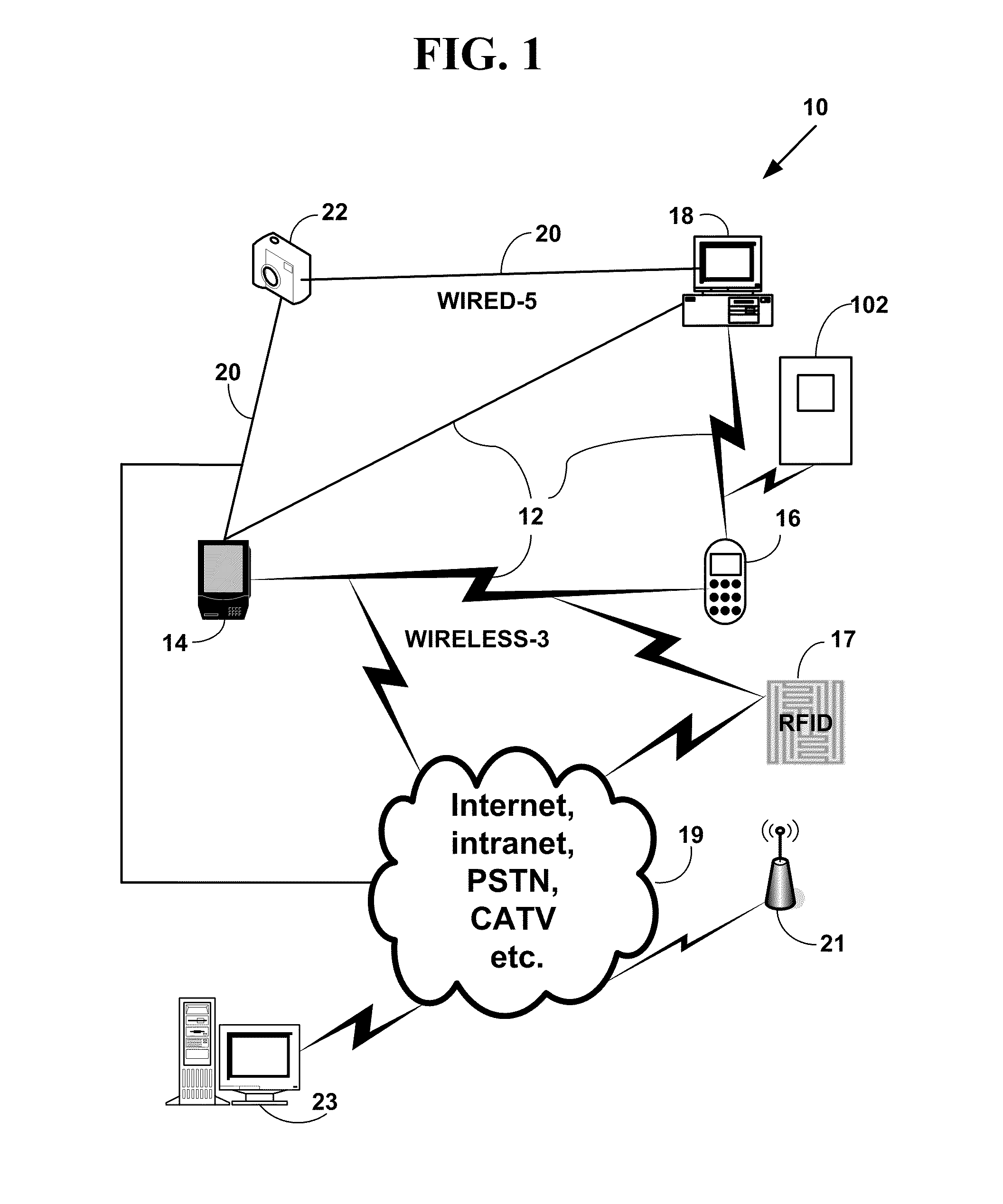
[0031]FIG. 1 is a block diagram of an exemplary mesh network 10. The mesh 12 includes a wireless component 3 and / or a wired component 5. A mesh network is a local area network (LAN) that employs one of two connection arrangements, “full mesh topology” or “partial mesh topology.” In the full mesh topology 12, each node is a mesh network device 14, 16, 18 is connected directly to each of the other mesh network device. In the partial mesh topology 20 some mesh network devices 22 are connected to all the others, but some of the mesh network devices 22 are connected only to those other mesh network devices 18 with which they exchange the most data. The connections can be wired or wireless in a mesh 12 network or partial mesh 20 network topologies. A mesh network is reliable and offers redundancy. If one mesh node can no longer operate, all the rest can still communicate with each other, directly or through one or more intermediate nodes. Mesh networks work we...


PUM


Abstract

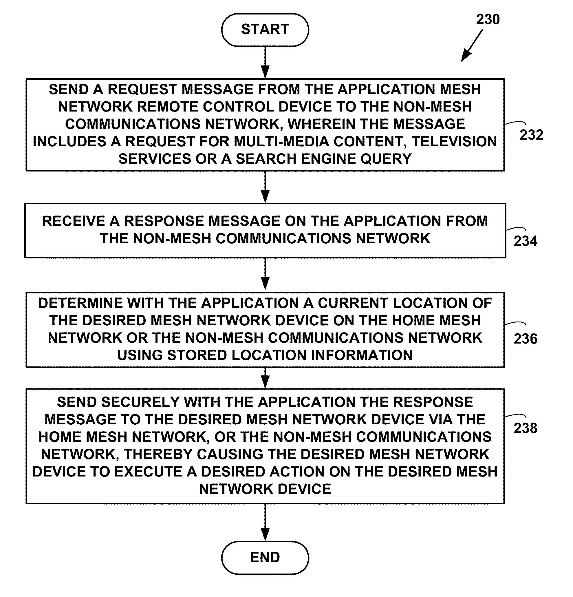
The mesh network remote control device is able to dynamically exchange information with other mesh network devices via a mesh network, partial mesh network, ad-hoc network or with an non-mesh network such as the Internet or an intranet. The mesh network remote control device controls devices connected to such mesh or non-mesh networks. The mesh network remote control device accepts commands from mesh network devices, non-mesh network devices, non-mesh communications networks (e.g., URLs, device commands, social networking logins, etc.), stores the original commands and transforms the original commands into simple display commands that are used by a user to control remote mesh network or non-mesh network devices.

Description

CROSS REFERENCES TO RELATED APPLICATIONS[0001]This application is a Continuation-In-Part (CIP) of U.S. utility patent application Ser. No. 12 / 884,521, filed on Sep. 17, 2010, which is a CIP of U.S. utility patent application Ser. No. 11 / 880,271, filed Jul. 20, 2007, that claims priority to U.S. Provisional Patent Application 60 / 833,741, filed Jul. 27, 2006, said application Ser. No. 11 / 880,271 issued as U.S. Pat. No. 7,801,058, on Sep. 21, 2010. This application also claims priority to U.S. Provisional application No. 61 / 331,454, filed May 5, 2010. The contents of all of the cited applications and the issued patent are incorporated by reference.FIELD OF THE INVENTION[0002]This invention relates to mesh networks, partial mesh networks and / or ad-hoc networks. More specifically, it relates to a mesh network remote control device.BACKGROUND OF THE INVENTION[0003]There are many types of computer and communications networks in existence. One variety of such networks is a mesh network.[000...

Claims


Application Information

Patent Timeline
Patent Type & Authority Applications(United States)
IPC IPC(8): G05B23/02
CPCH04L63/0428H04L67/18H04L63/08H04L63/101H04L63/102H04W4/02H04W4/023H04W4/20H04W12/02H04W12/10H04W76/023H04W84/18H04L67/306H04L67/12H04L63/06H04W76/14H04W12/033H04L67/52H04L41/22
Inventor WANG, RAY
Owner III HLDG 2
Learn More