Radio base station and radio communication method

a radio communication and base station technology, applied in the field of radio base stations and radio communication methods, can solve problems such as communication delay, header compression may not work well, and failure to work properly

Inactive Publication Date: 2011-09-01
KYOCERA CORP
View PDF1 Cites 10 Cited by
  • Summary
  • Abstract
  • Description
  • Claims
  • Application Information

AI Technical Summary

Benefits of technology

The present invention provides a radio base station and a radio communication method that can avoid failures and application failures when different radio base stations serve as the uplink and downlink radio communication partner of a radio terminal. The radio base station can transmit a handover instruction to the radio terminal if the uplink or downlink traffic value exceeds a predetermined value, and can also compare the traffic value with an uplink threshold for the specific application and transmit the handover instruction only if the threshold is exceeded. This avoids failures and application failures caused by differences in the uplink and downlink radio communication partner.

Problems solved by technology

However, in a radio communication system in which different radio base stations can serve as an uplink radio communication partner and a downlink radio communication partner, there are problems to be described hereinafter, if an uplink radio communication partner and a downlink radio communication partner are selected only depending on radio communication.
In this situation, if the radio terminal hands over the uplink radio communication partner or the downlink radio communication partner to another radio base station, communication delay occurs with the aforementioned handover.
Furthermore, in an application which uses a header compression protocol, header compression may not function well if an uplink radio communication partner and a downlink radio communication partner are different.
As such, in a radio communication system in which different radio base stations can serve as an uplink radio communication partner and a downlink radio communication partner, there is a problem that a failure may occur depending on an application run by a radio terminal if the uplink radio communication partner and the downlink radio communication partner are different radio base stations.
On the one hand, if there is much traffic being transmitted and received through the radio base station, much communication resources in the uplink or downlink are consumed.
That is to say, there is a problem that a radio base station cannot normally continue the service when communication resources in the uplink or downlink fall short.

Method used


Image

  • Radio base station and radio communication method
  • Radio base station and radio communication method
  • Radio base station and radio communication method

Examples


Embodiment Construction

[0041]A radio communication system according to an embodiment of the present invention will be described hereinafter with reference to the drawings. Specifically, (1) an overall schematic configuration, (2) a configuration of a radio base station, (3) an operation of a radio base station, (4) advantageous effects, and (5) other embodiments will be described. In the following description of the drawings of embodiments, a same or similar reference numeral is given to a same or similar part.

[0042](1) Overall Schematic Configuration

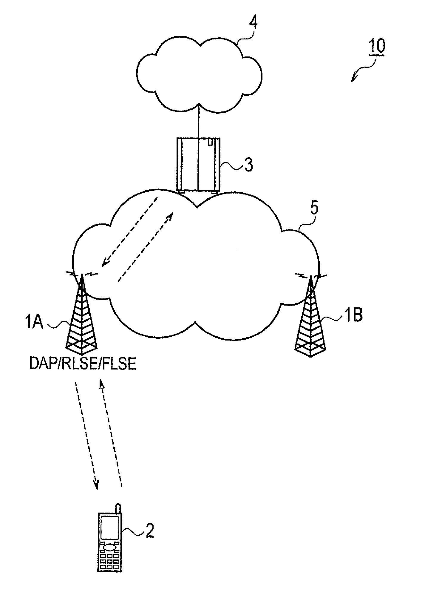
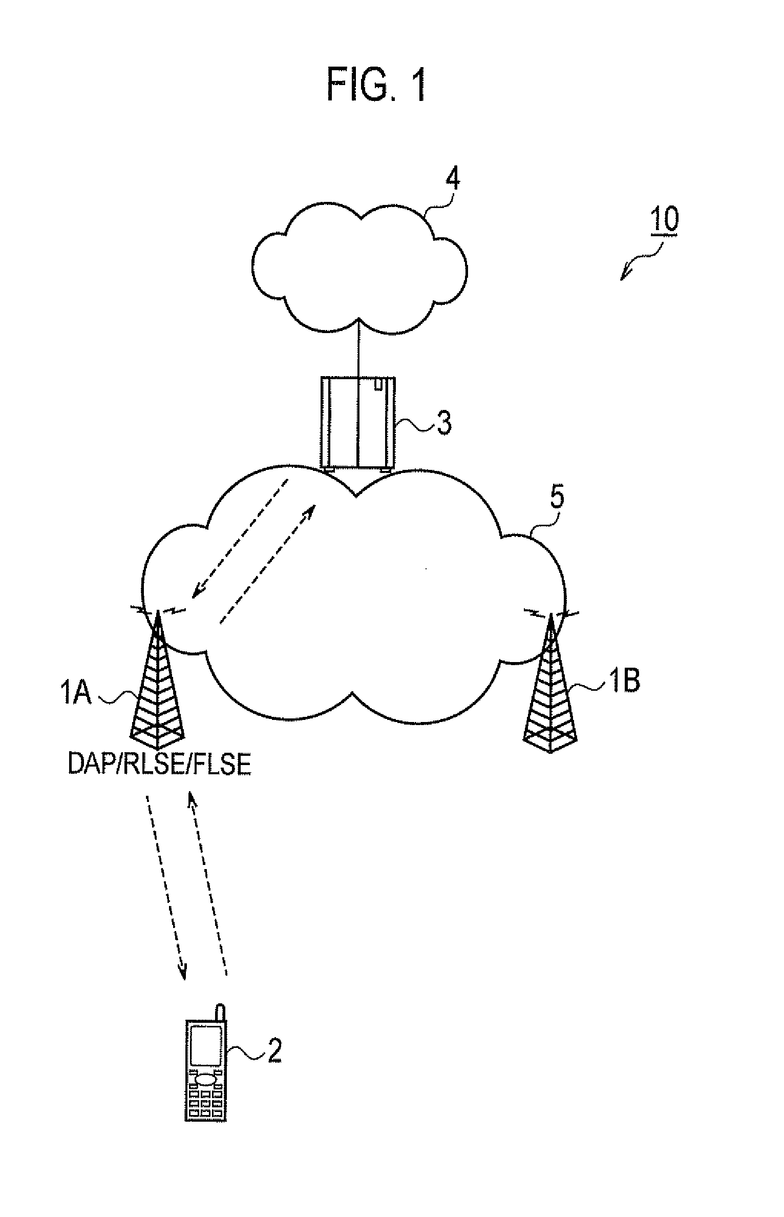
[0043]FIG. 1 is an overall schematic configuration diagram of a radio communication system 10 according to the present embodiment.

[0044]As shown in FIG. 1, a radio communication system 10 includes a radio base station 1A, a radio base station 15, a radio terminal 2, a network gateway 3, and an IP network 4 (communication network). In the embodiment, the radio communication system 10 has a configuration based on 3GPP2 (Third Generation Partnership Project 2) U...


PUM


Abstract

A radio base station, comprising a DAP / RLSE / FLSE judging unit configured to judge whether the radio base station functions as both RLSE and FLSE, an application judging unit configured to judge whether the application running on the radio terminal is a specific application, and a handover instruction transmission unit configured to transmit a handover instruction to the radio terminal to handover either the RLSE or FLSE to another radio base station, when it is determined that the radio base station functions both as RLSE and FLSE and the running application is not the specific application.

Description

TECHNICAL FIELD[0001]The present invention relates to a radio base station and a radio communication method used in a radio communication system in which different radio base stations can serve as a radio communication partner of a radio terminal in an uplink and a radio communication partner of the radio terminal in a downlink.BACKGROUND ART[0002]In general, in a radio communication system, a same radio base station serves as a radio communication partner (hereinafter referred to as an “uplink radio communication partner”) of a radio terminal in an uplink from the radio terminal to a communication network and a radio communication partner (hereinafter referred to as a “downlink radio communication partner”) of the radio terminal in a downlink from the communication network to the radio terminal.[0003]In recent years, provision of a radio communication system in which different radio base stations can serve as an uplink radio communication partner and a downlink radio communication ...

Claims


Application Information

Patent Timeline
Patent Type & Authority Applications(United States)
IPC IPC(8): H04W36/00H04W24/00
CPCH04W36/08H04W36/38H04W36/24
Inventor MURAKAMI, KEIJIFUJITO, KYOKOMATSUNAMI, HIROKAZU
Owner KYOCERA CORP
Why Eureka
Try Eureka