Mobile robot and controller for same

a technology of mobile robots and controllers, applied in the direction of electric programme control, program control, instruments, etc., can solve the problems of mobile robots not being able to remotely control by radio, mobile robots not being able to return to a communication-feasible area, etc., to achieve the effect of easy detection and reduced radio intensity

Active Publication Date: 2012-05-15
HONDA MOTOR CO LTD
View PDF29 Cites 127 Cited by
  • Summary
  • Abstract
  • Description
  • Claims
  • Application Information

AI Technical Summary

Benefits of technology

[0020]Another object of the present invention is to provide a mobile robot that can move autonomously to a place where radio communication can be restored if having moved to a place where radio communication is cut off, and a controller for the mobile robot.
[0107]With this structure, because the mobile robot has the movement speed limited depending on the radio environment state of communication with the radio base station, communication cutoff is prevented from happening during movement.

Problems solved by technology

Such a mobile robot cannot be remotely controlled by radio if the mobile robot has been moved outside the reaching range of radio waves, and a person needs to take the mobile robot back to within the reaching range of radio waves by hand.
However, because the mobile robot described in the reference 1 selects a movement path based on the radio wave intensity map, the mobile robot may not be able to return to a communication-feasible area if communication is cut off by a cause other than radio wave intensity such as noise.
As to the mobile robot described in the reference 2, where only one mobile robot is operating, the mobile robot cannot have communication with the base station relayed, and when having moved outside the reaching range of radio waves, the mobile robot may not be able to return to a communication-feasible area.
With this technique, there is the problem that, because radio communication can be cut off by a cause other than radio wave intensity such as noise, radio communication may not be restored depending on the radio environment even if the mobile robot has moved to a place where radio waves are enough in intensity.
With the technique of the reference 2, there is the problem that, where only one mobile robot is operating, radio communication cannot be restored if the mobile robot has moved outside the reaching range of radio waves.
However, with the conventional art, when the robot has moved to a point where the radio environment is bad, the following problems occur:
If a human (user) near the robot observes the robot moving, he / she cannot determine whether the robot is moving toward a workplace to work or from a position where the radio wave state is bad to a position where good.
Thus, when giving a new instruction to the robot moving, the user cannot confirm whether the robot has correctly received the new instruction.
For example, if the robot cannot receive personal information of a detected human from the managing computer, a failure occurs in communication with the detected human.
In such a case, humans near the robot cannot determine whether the change in the robot's response is caused by a failure or degradation in the radio environment or whether it is intended in design.
Thus, they cannot determine how to deal with it.
As such, there is the problem that the utility (variance of freedom) of the robot is reduced because the radio wave state cannot be recognized.
In other words, restoration of the radio communication such as cut off cannot be provided.
That is, there is the problem that a human has to analyze the cause to restore the robot, which makes the robot difficult to use.

Method used


Image

  • Mobile robot and controller for same
  • Mobile robot and controller for same
  • Mobile robot and controller for same

Examples


first embodiment

Configuration of Robot

[0208]FIG. 5 is a block diagram showing the configuration of a robot according to a first embodiment.

[0209]As shown in FIG. 5, the robot R includes cameras C, a speaker S, a microphone MC, an image processor 110, a voice processor 120, a main controller 139, an autonomous movement controller 148, a radio communication unit 160, and a surroundings-state detector 170 as well as the legs R1, the torso R2, the arms R3, and the head R4.

[0210]The robot R further includes a gyro sensor SR1 for detecting directions and / or a GPS (Global Positioning System) receiver SR2 for detecting coordinates as a self-position detecting unit for detecting its own position.

[Camera]

[0211]The cameras (image pickup units) C are for reading in images in the form of digital data and are embodied by, for example, color CCD (Charge Coupled Device) cameras. The cameras C are arranged laterally in parallel, and the images picked up are output to the image processor 110. The cameras C, speaker ...

second embodiment

[0460]Next, a mobile robot of a second embodiment will be described with reference to the drawings. The basic structure of the mobile robot of the second embodiment is the same as that of the mobile robot of the first embodiment, and differences from the latter will be mainly described.

[0461]In description, the same elements are indicated by the same reference numerals with duplicate description being omitted.

[Mobile Robot Control System]

[0462]First, a mobile robot control system A of the second embodiment will be described.

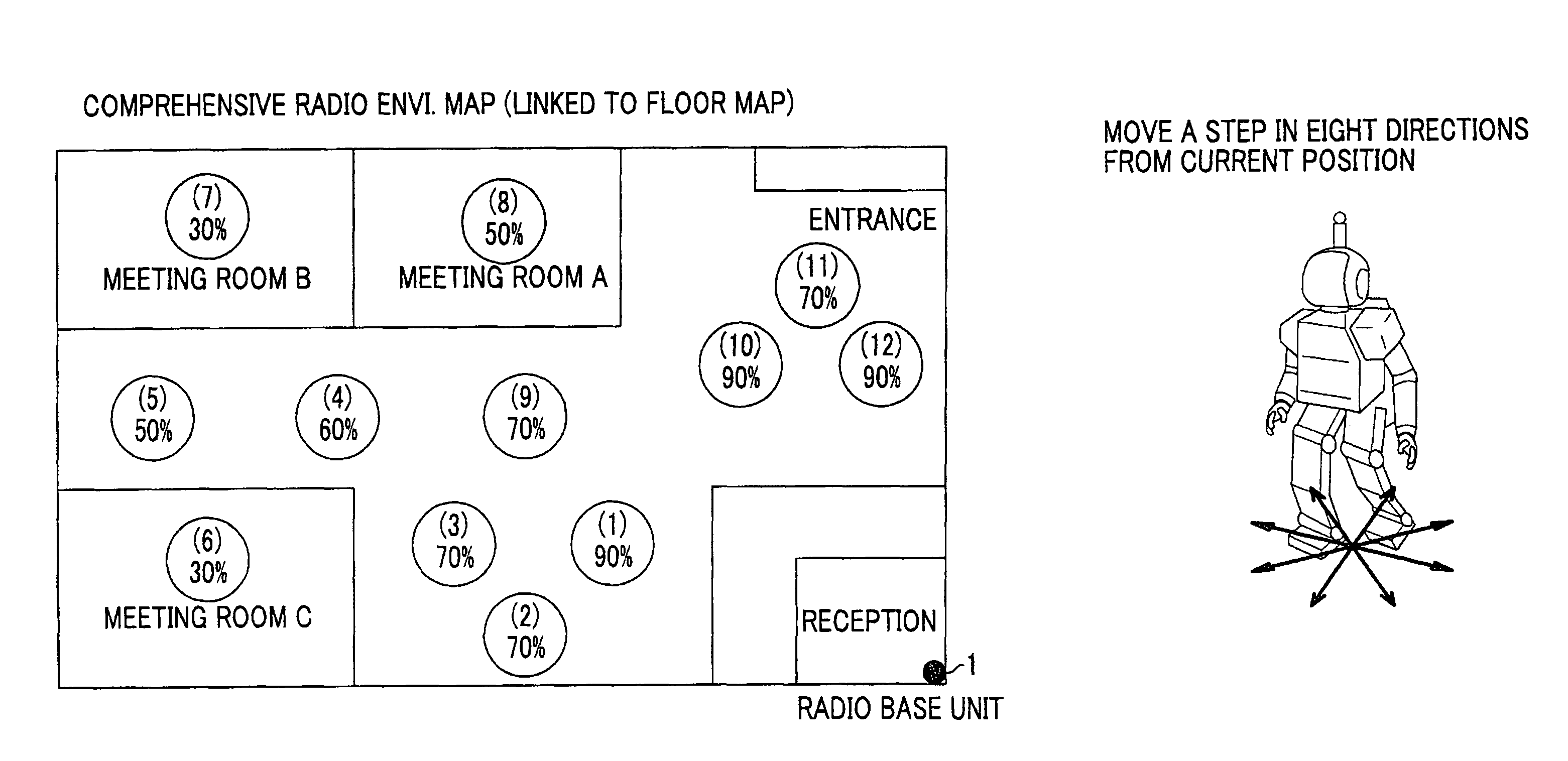
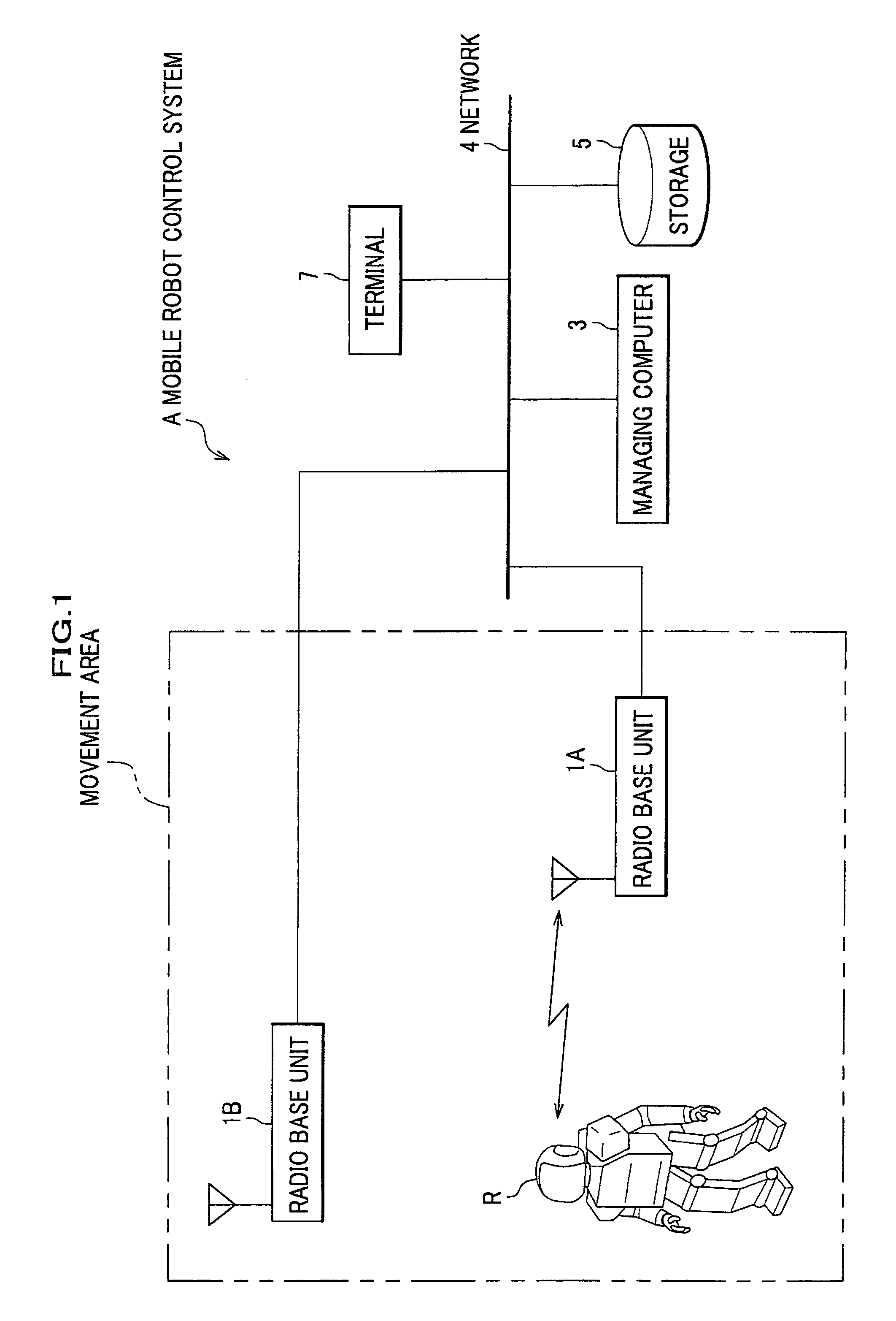
[0463]As shown in FIG. 1, the mobile robot control system A comprises a mobile robot R (hereinafter a “robot” for short) provided in a movement area where to execute a task; a radio base unit (radio base station) 1 (1A, 1B) linked to the robot R by radio communication; a managing computer 3 connected to the radio base unit 1 via a network 4; and a storage 5 and a terminal 7 connected to the managing computer 3 via the network 4. The numbers of mobile robots R and...

third embodiment

[0640]Next, a mobile robot of a third embodiment will be described with reference to the drawings. The basic structure of the mobile robot of the third embodiment is the same as that of the mobile robots of the first and second embodiments, and differences from the latter will be mainly described.

[Mobile Robot Control System]

[0641]First, a mobile robot control system of the third embodiment will be described. FIG. 39A is a block diagram of the mobile robot control system of the embodiment of the present invention.

[0642]As shown in FIG. 1 and FIG. 39A, the mobile robot control system A comprises a mobile robot R provided in a movement area where to execute a task; a radio base unit 1 linked to the mobile robot R by radio communication; a managing computer 3, a storage 5, and a terminal 7 connected to the radio base unit 1 via a network 4. The numbers of mobile robots R and radio base units 1 provided in a movement area where to execute a task are not limited to this embodiment.

[0643]...


PUM


Abstract

A mobile robot includes a radio communication unit; a radio environment detector detecting plural types of radio environment data indicating the degree of goodness of radio environment, a comprehensive radio environment data being calculated from results of weighting the plural types of radio environment data with predetermined weights; a self-position detecting unit; a storage for map data of a movement area; the calculated comprehensive radio environment data being written in association with its own position detected. The robot moves at a movement speed not higher than the maximum movement speed determined so that communication with the radio base station is not cut off during movement and, if radio communication is cut off, searches the radio environment map for a communication restoration position where the radio communication is feasible to establish and moves to the communication restoration position and has the radio intensity reporting control section reporting the determined level of radio intensity.

Description

CROSS-REFERENCE TO RELATED APPLICATIONS[0001]The present application claims priority from Japanese Patent Application Nos. 2006-270374, 2006-270375, 2006-270376, and 2006-270377 filed on Oct. 2, 2006, which are herein incorporated by reference.BACKGROUND OF THE INVENTION[0002]1. Field of the Invention[0003]The present invention relates to a mobile robot that moves while communicating by radio with a managing computer and a controller for the same.[0004]2. Description of the Related Art[0005]In recent years, a technique of issuing a task execution command signal to a mobile robot to have it execute a task has been proposed. Such a mobile robot cannot be remotely controlled by radio if the mobile robot has been moved outside the reaching range of radio waves, and a person needs to take the mobile robot back to within the reaching range of radio waves by hand.[0006]As to this problem, in Japanese Patent Application Laid-Open Publication No. 2004-260769 (hereinafter called a reference 1...

Claims


Application Information

Patent Timeline
Patent Type & Authority Patents(United States)
IPC IPC(8): H04B7/26G05D1/02H04W16/20G06F19/00H04W16/00
CPCG01S5/0252G05D1/0251G05D1/028G06N3/008G05D2201/0217G01S5/02524
Inventor SAITO, YOKOKAWABE, KOJI
Owner HONDA MOTOR CO LTD
Why Eureka
Try Eureka