Automatic GPS tracking system with passive battery circuitry

a tracking system and passive battery technology, applied in power management, instruments, high-level techniques, etc., can solve the problems of high power consumption of rf transceivers, inability to accurately track objects, and inability to accurately detect objects, etc., to achieve low power consumption.

Inactive Publication Date: 2008-10-09
GHAZARIAN OHANES D
View PDF7 Cites 131 Cited by
  • Summary
  • Abstract
  • Description
  • Claims
  • Application Information

AI Technical Summary

Benefits of technology

[0032]The primary object of the invention is to provide a GPS tracking system worn or installed on persons for tracking or assets with a global positioning receiver utilizing two separate batteries for the power supply. The invention consists of a GPS tracking unit, having a processor, a GPS receiver and a satellite or cellular modem and a low power consumption RF transceiver. The GPS tracking unit utilizes a first battery for its power supply, communicating with an RF signal at time intervals with a home base station RF transceiver unit, located in a pre-selected area within the communication range of the GPS tracking unit.

Problems solved by technology

This prior art necessitates constant battery consumption, requiring frequent battery charging or replacement, in order for the GPS receiver to receive satellite signals, the comparator to function and the wireless modem to receive and transmit a signal.
Contrary to teachings found in the prior arts where a “Sleep mode” or “power saver” mode or “standby” mode methods has been utilized, which each one of such teaching methods drains constant low current consumption from the battery, and if presumably an external power On / Off switch was used in the prior arts to control unnecessary power drain from the battery, by user turning manual On / Off switch to control GPS tracking power circuitry, that presumption will not be practical in use at all, because subject to be monitored before leaving a selected proximity area may forget to turn On the GPS unit power switch, and the art becomes completely useless.

Method used


Image

  • Automatic GPS tracking system with passive battery circuitry
  • Automatic GPS tracking system with passive battery circuitry
  • Automatic GPS tracking system with passive battery circuitry

Examples


Embodiment Construction

[0048]The best mode for carrying out the invention is presented in the terms of a embodiment, preferred embodiment and an alternate embodiment.

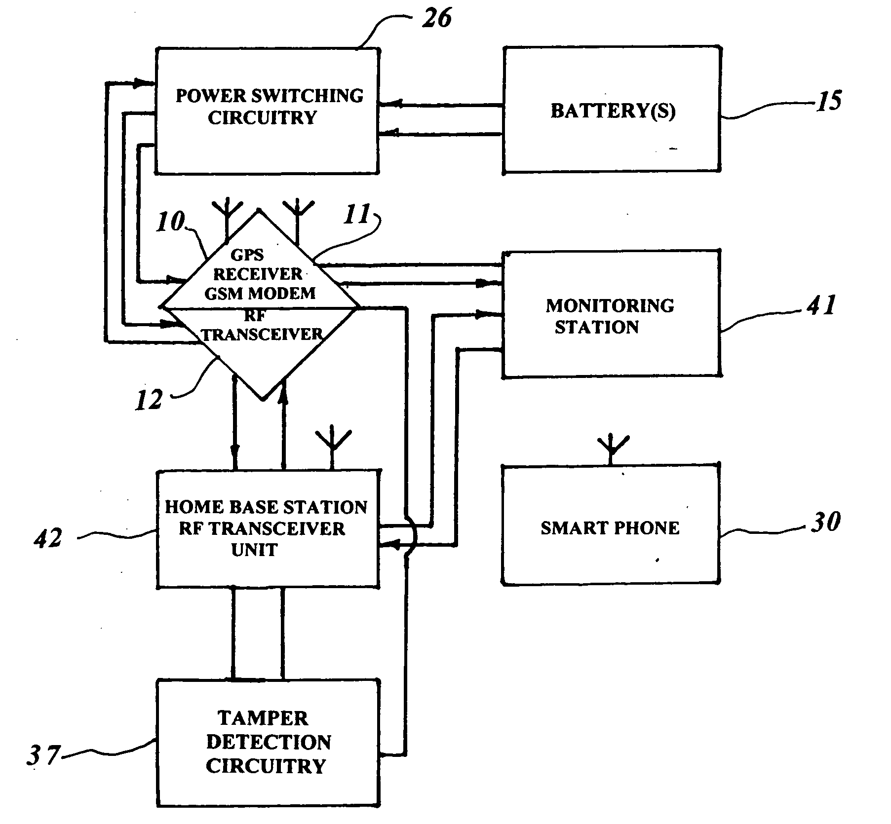
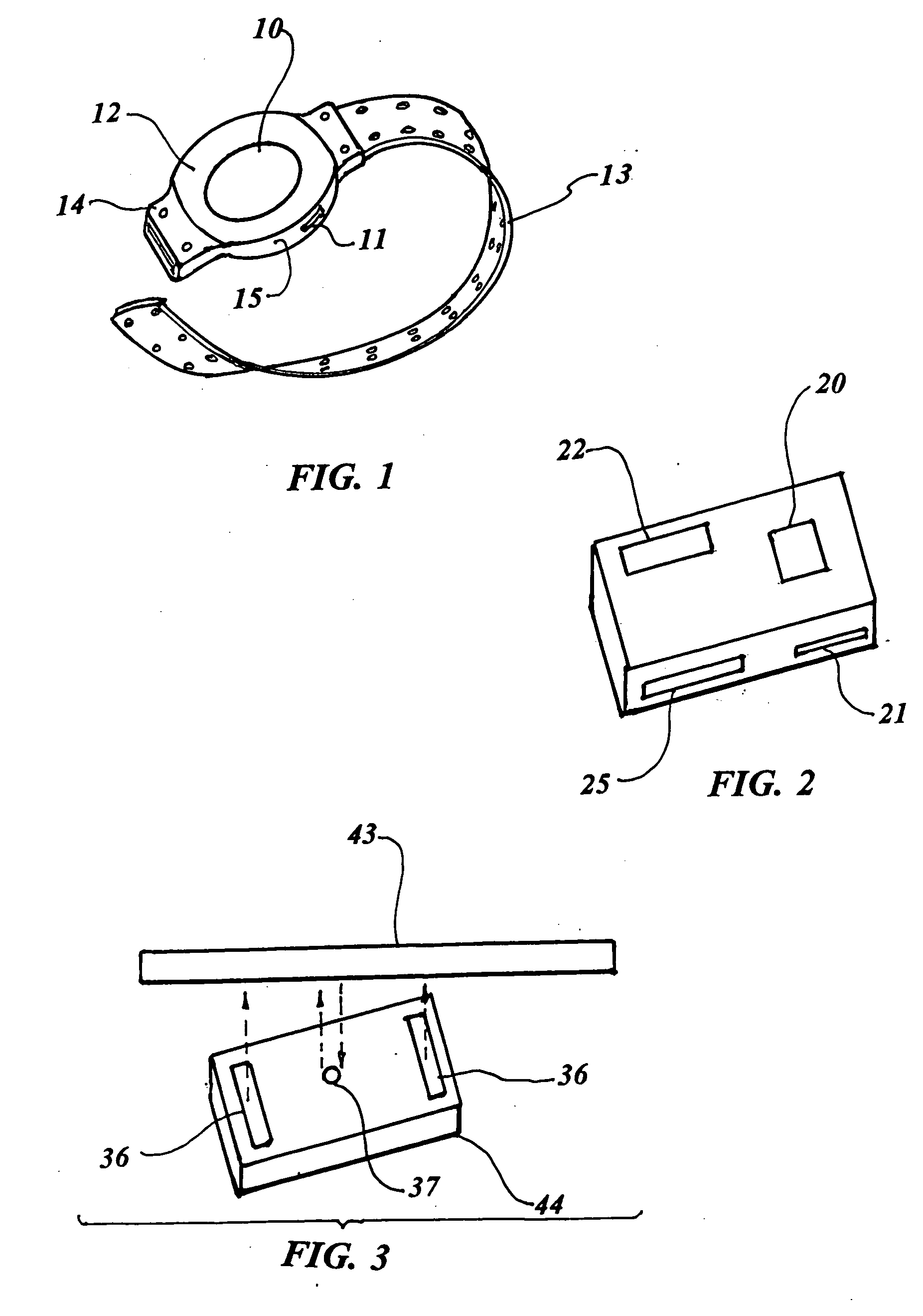
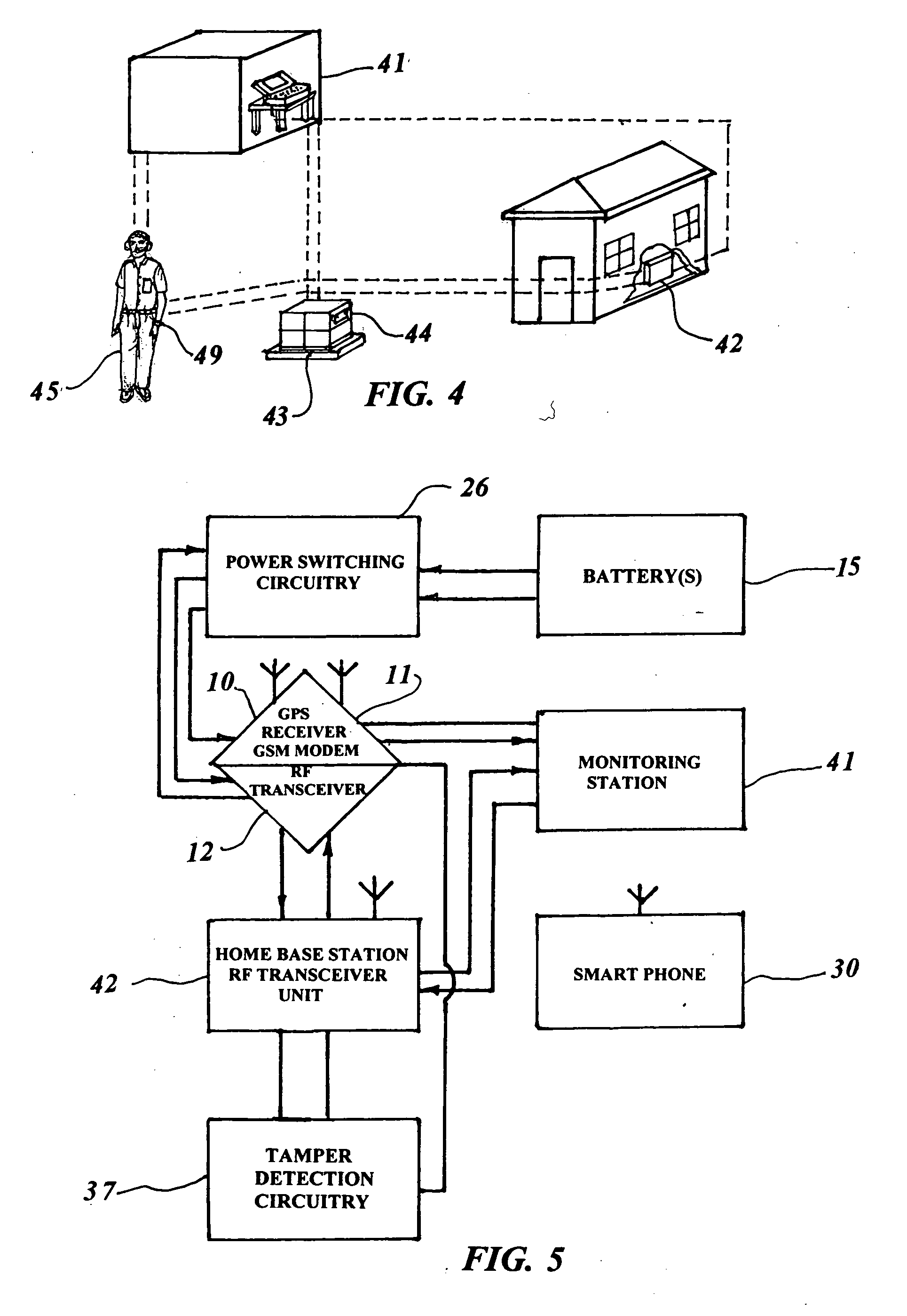
[0049]The embodiment of a GPS tracking system is shown in FIGS. 1 thorough 5 and is comprised of FIG. 4 a portable battery operated GPS tracking unit 44 to be mounted on an asset 43 or attached to a person 45, wrist or ankle 49. The GPS tracking unit 44, FIGS. 1 and 2 includes a GPS receiver 10, 20, and a cellular or satellite modem 11, 21. Incorporated in the GPS tracking unit, is a low power consumption RF transceiver 12, 22 using a battery 15, 25 or dual batteries, the first battery 15 preferably Li-Ion rechargeable battery provides power to the low power RF transceiver 12, 22, And provides power to a GPS receiver 10, 20 and a wireless communication modem 11, 21 which is also included in the tracking unit 44,49. The low power consumption RF transceiver 12,22 communicates at time intervals with a FIG. 4 home base station RF transceiver unit...


PUM


Abstract

An automatic GPS tracking system is taught that consists of a GPS tracking unit secured to a person or an asset that includes a GPS receiver and a first battery operated a processor and first RF transceiver which emits an RF signal. A home base station receives the RF signal within a pre-selected proximity communication distance. A monitoring station which is in communication from a cellular modem or a satellite modem within the GPS tracking unit such that, if a person or asset having the tracking system secured thereon moves beyond the a pre-selected proximity communication distance from a home base unit, the first transceiver RF communication signals is lost, the processor automatically powers “on” the second battery to power up the GPS receiver and the cellular modem, and the GPS tracking unit may signal the monitoring station which displays the location of the person or asset.

Description

CROSS REFERENCE TO RELATED APPLICATION[0001]This application is a Continuation-In-Part of patent application Ser. No. 11 / 411,164 filed Apr. 25, 2006.TECHNICAL FIELD[0002]The present invention relates to tracking of objects to provide location information. More specifically, the present invention relates to a GPS tracking system worn or installed on persons, or assets utilizing one or preferably two separate batteries as a power supply, which definitely provides an improvement to the art.BACKGROUND OF THE INVENTION[0003]The invention is for tracking of individuals or assets to provide knowledge of their location with tracking GPS tags. When the subject or asset to be monitored moves away from a dedicated area, the invention provides automatic GPS monitored using a GPS unit that does not require frequent battery charging or replacement.[0004]When the subject or asset to be monitored leaves a home base unit dedicated area, the GPS unit RF transceiver circuitry within predetermined time...

Claims


Application Information

Patent Timeline
Patent Type & Authority Applications(United States)
IPC IPC(8): G01S5/14H04B1/38G01S19/09G01S19/16G01S19/34G01S19/35
CPCG08B25/016H04W52/0241G01S19/16G01S19/34G08B13/1427G08B21/0202Y02D30/70
Inventor GHAZARIAN, OHANES D.
Owner GHAZARIAN OHANES D
Why Eureka
Try Eureka