Radio communication system, radio communication method, radio communication device, reception device, and program

a radio communication system and radio communication technology, applied in the field of radio communication systems, radio communication methods, radio communication devices, reception devices, and programs, can solve the problems of inability to flexible resource allocation using time-and-frequency axes, high peak power, transmission-power amplifying, etc., and achieve excellent frequency utilization efficiency.

Active Publication Date: 2011-09-01
SHARP KK
View PDF33 Cites 21 Cited by
  • Summary
  • Abstract
  • Description
  • Claims
  • Application Information

AI Technical Summary

Benefits of technology

[0092]According to the present invention, even when SC-ASA is adapted to transmission from multiple transmission devices or MIMO transmission, adequate subcarriers can be selected, and thereby excellent frequency utilization efficiency can be achieved.

Problems solved by technology

However, the high peak power is a fatal problem for uplink communication (from the mobile station device to the base station device) having a relatively-low transmission-power amplifying function.
However, the use of the single-carrier scheme causes a problem that flexible resource allocation using time-and-frequency axes cannot be performed such as in the case of OFDM.
However, MIMO transmission causes signals transmitted from the two transmission systems to interfere with each other on the receiving side.
However, a replica of the firstly received signal cannot be generated.

Method used


Image

  • Radio communication system, radio communication method, radio communication device, reception device, and program
  • Radio communication system, radio communication method, radio communication device, reception device, and program
  • Radio communication system, radio communication method, radio communication device, reception device, and program

Examples


first embodiment

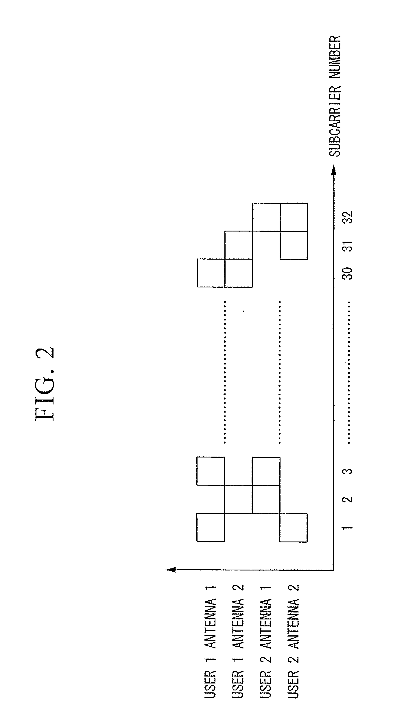
[0227]A first embodiment explains a method of determining subcarriers used for transmitting data from respective antennas based on channel conditions for respective subcarriers and for respective antennas. A radio communication system of the first embodiment includes multiple mobile station devices and a base station device. The base station device is a reception device of the first embodiment. The mobile station device is a transmission device of the first embodiment. The number of mobile station devices simultaneously connected to the base station device is two. The number of transmission antennas included in each mobile station device is also two. Signals are transmitted from a total of four transmission antennas.

[0228]A transmission method used by the mobile station device is DFT-S-OFDM. The total number of subcarriers is 32. The number of subcarriers used for each antenna of each mobile station device is 16. The number of reception antennas of the base station device is also tw...

second embodiment

[0251]The second embodiment explains a configuration of a reception device to which SC / MMSE (Soft Canceller / MMSE)-technique is applied, in which with respect to single-user-MIMO-and-multi-user-MIMO-mixed signals subjected to the spatial-and-spectral mapping of the present invention, replicas of received signals are generated based on the reliability of demodulated data, unnecessary interference (replicas) are subtracted from the received signals, and then a series of operations, such as equalization and demodulation, is repeated, thereby gradually increasing the reliability of the demodulated data.

[0252]Similar to the first embodiment, it is assumed in the second embodiment that the number of mobile station devices simultaneously connected to the base station device is two. The number of transmission antennas included in each mobile station device is also two. Signals are transmitted from a total of four transmission antennas. A transmission method used by the mobile station device ...

third embodiment

[0282]The first and second embodiments have explained the case where spatial-and-spectral mapping is performed under the condition that there are always two signals to be multiplexed onto each subcarrier. As explained in those embodiments, if signals interfering with one another can be cancelled on the receiving side, spectral mapping may be independently performed for each antenna on each transmitting side in consideration of only a channel variation. The following embodiment explains a mapping method of each transmission antenna independently determining a spectrum to be used when the number of signals to be multiplexed is not limited as in the first and second embodiments.

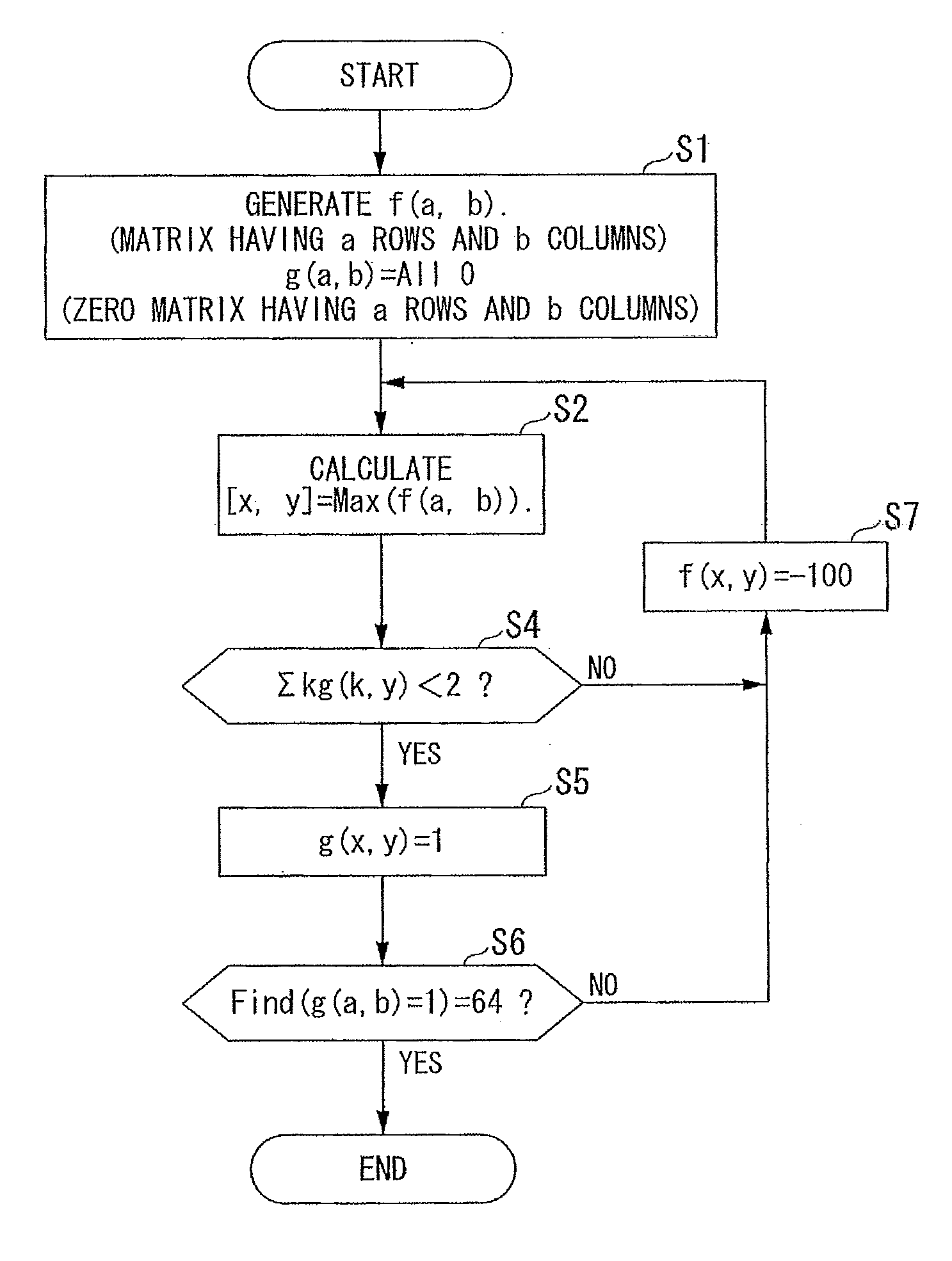
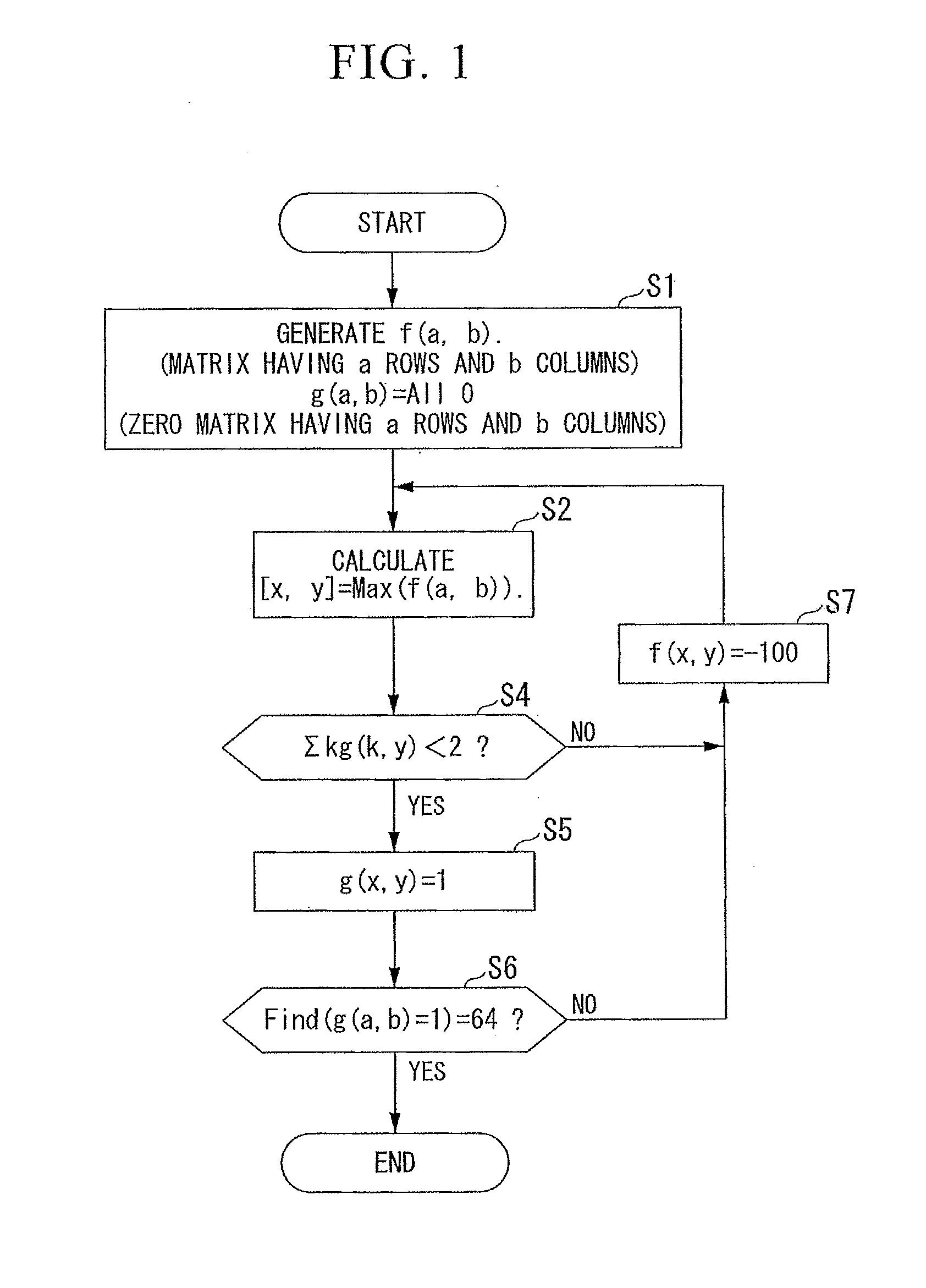
[0283]FIG. 10 illustrates a flow for determining subcarriers to be used for implementing the third embodiment. Like reference numerals denote like operations in FIGS. 1 and 10. The difference from FIG. 1 is that the operation in step S4 is deleted. This difference depends on the fact that the limit of the number...


PUM


Abstract

Each of first radio communication devices includes; a frequency spread unit which spreads frequency of a transmitted signal to generate a frequency-spread signal; and a mapping unit which allocates the frequency-spread signal to a subcarrier according to the mapping information which specifies a subcarrier. A second radio communication device includes: a demapping unit which extracts from a received signal a signal of the subcarrier specified by the mapping information; and an inverse frequency spread unit which inverse-frequency-spreads the extracted signal. The first radio communication device or the second radio communication device includes a use subcarrier decision unit that decides a subcarrier to which the frequency-spread-signal is allocated according to a communication path capacity of each subcarrier of each antenna used for transmission by the first radio communication devices and generates mapping information used to specify the decided subcarrier.

Description

TECHNICAL FIELD[0001]The present invention relates to a radio communication system, a radio communication method, a radio communication device, a reception device, and a program.[0002]Priority is claimed on Japanese Patent Application Nos. 2007-210936 and 2007-210937, both filed Aug. 13, 2007, the content of which are incorporated herein by reference.BACKGROUND ART[0003]Recently, next-generation mobile communication systems have been actively studied. As a method for enhancing the frequency utilization efficiency of a system, a single-frequency reuse cellular system has been proposed in which each cell uses the same frequency band so that each cell can use the entire band allocated to the system.[0004]OFDMA (Orthogonal Frequency Division Multiple Access) is a front-runner in a downlink (communication from a base station device to a mobile station device). OFDMA is a communication system in which information data are modulated by use of different modulation schemes, such as 64 QAM (6...

Claims


Application Information

Patent Timeline
Patent Type & Authority Applications(United States)
IPC IPC(8): H04B7/24
CPCH04L5/0026H04L5/0037H04L25/0204H04L25/022H04L25/0242H04L25/03159H04W72/0446H04L25/03318H04L27/2607H04L27/2615H04L2025/03414H04L2025/03426H04L25/03171H04L5/0007H04L5/0044H04W72/0453
Inventor YOKOMAKURA, KAZUNARIHAMAGUCHI, YASUHIROTO, SHIMPEIKUBOTA, MINORUNAMBA, HIDEOSAMPEI, SEIICHIMIYAMOTO, SHINICHIIBI, SHINSUKE
Owner SHARP KK
Why Eureka
Try Eureka