

Thermal Athletic Glove
- Summary
- Abstract
- Description
- Claims
- Application Information
AI Technical Summary
Benefits of technology
Problems solved by technology
Method used
Image

Examples
Embodiment Construction
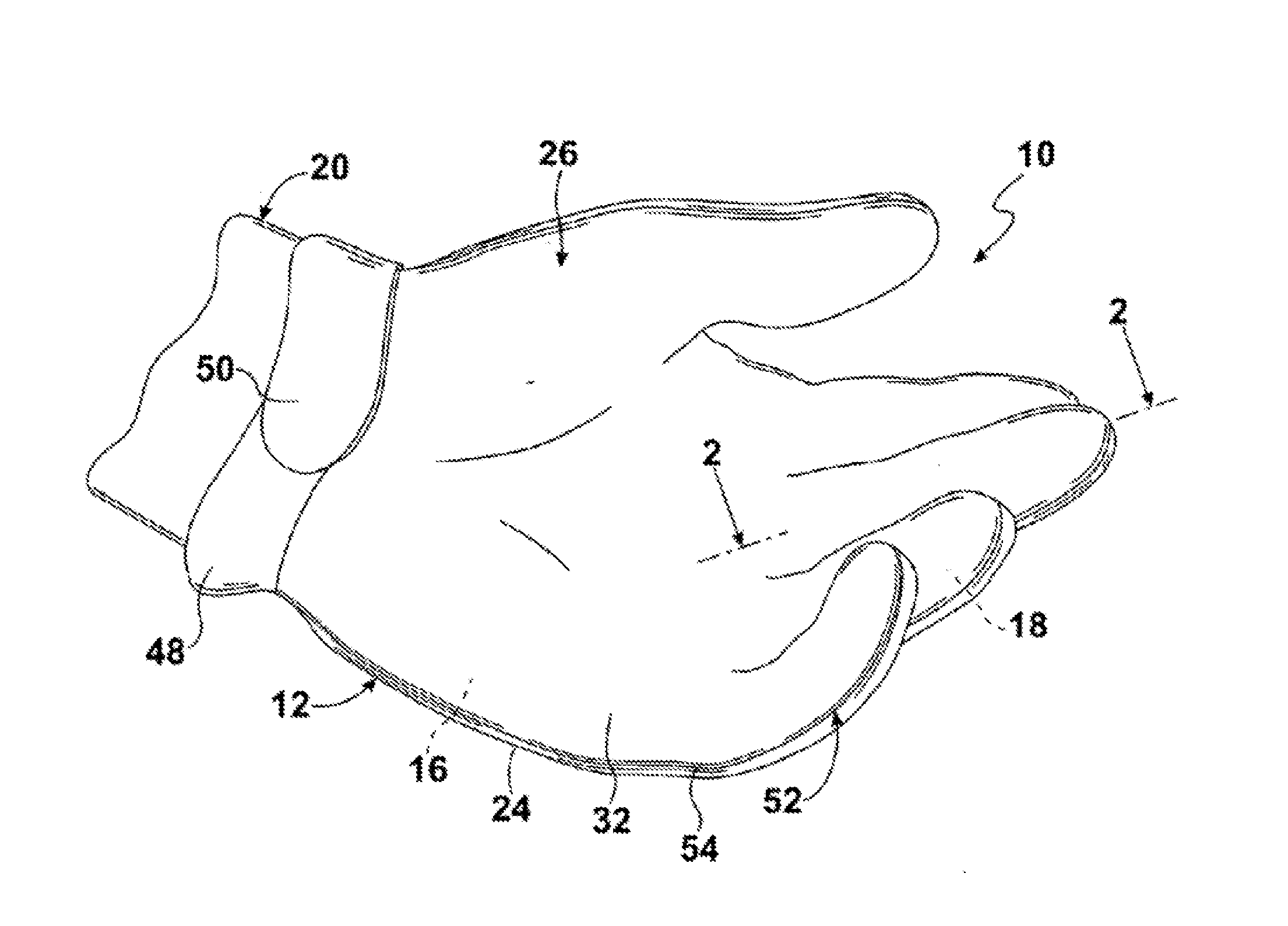
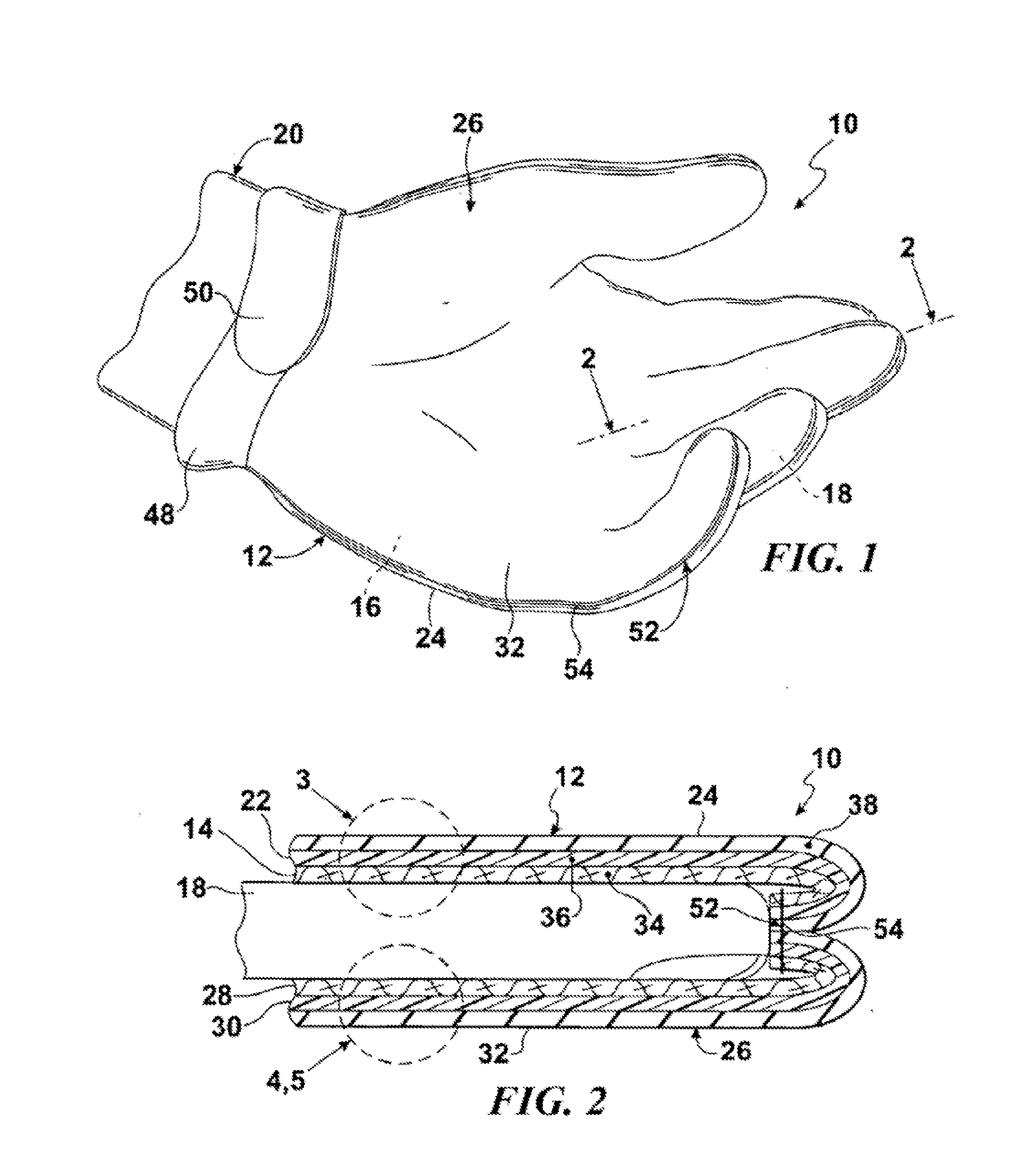
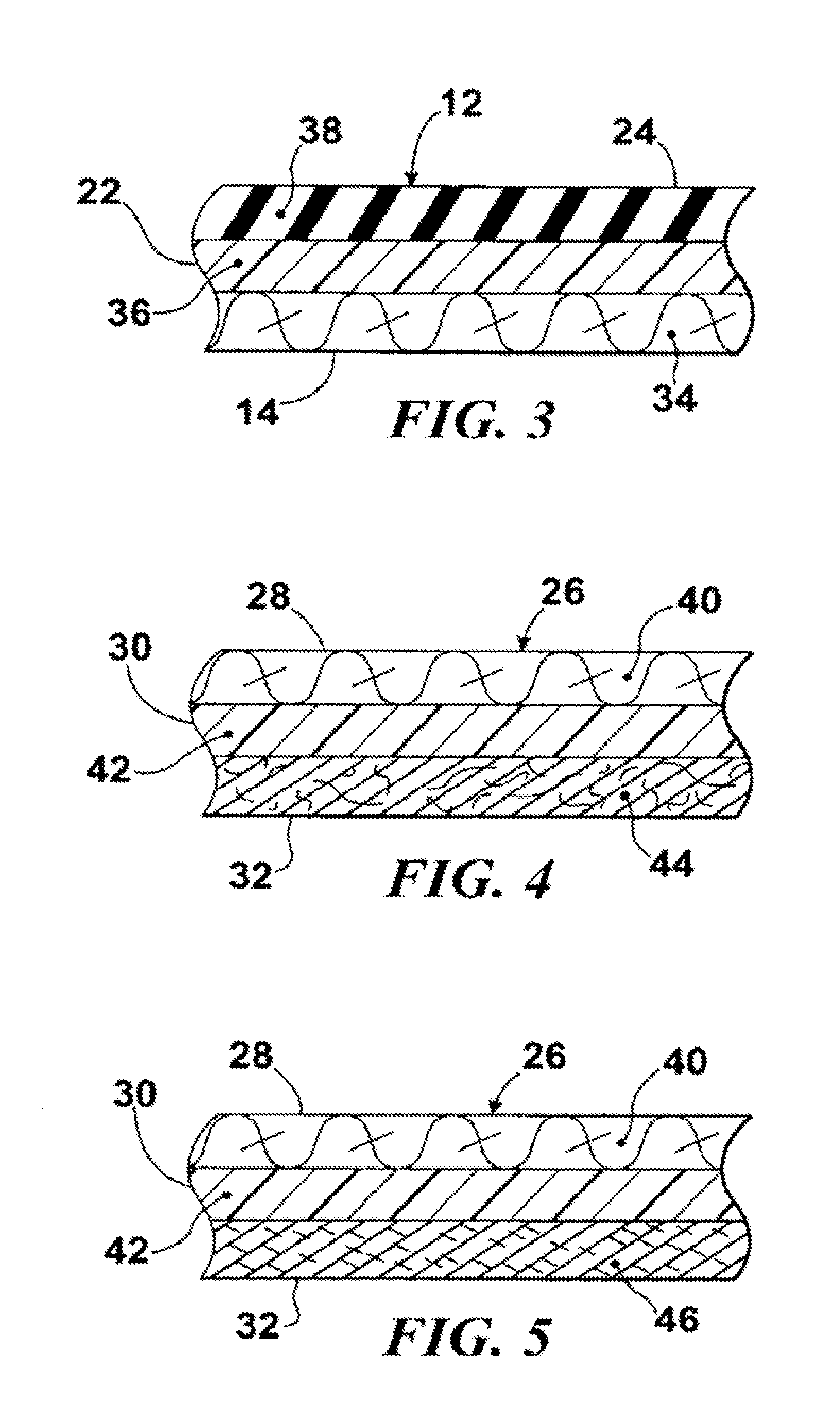
[0053]Referring now to the figures, in which like numerals indicate like parts, and particularly to FIGS. 1 through 5, which are a diagrammatic perspective view of an embodiment of the present invention; an enlarged diagrammatic cross-sectional view taken on line 2-2 in FIG. 1; a further enlarged diagrammatic cross-sectional view, taken in the area enclosed in the dotted circle indicated by arrow 3 in FIG. 2, showing the particular materials which are incorporated in the back side portion of the present invention in greater detail; a further enlarged diagrammatic cross-sectional view, taken in the area enclosed in the dotted circle indicated by arrow 4 in FIG. 2, showing the particular materials which are incorporated in the palm side portion of a first embodiment of the present invention in greater detail; and a further enclosed diagrammatic cross-sectional view, taken in the area enclosed in the dotted circle indicated by arrow 5 in FIG. 2, showing the particular materials which a...
PUM
| Property | Measurement | Unit |
|---|---|---|
| Metallic bond | aaaaa | aaaaa |
| Water resistance | aaaaa | aaaaa |
| Thermal properties | aaaaa | aaaaa |
Abstract
Description
Claims
Application Information