
Battery charging system and method

a battery charging and battery technology, applied in the field of battery charging system and method, can solve the problem that rechargeable batteries are at risk of being damaged

Inactive Publication Date: 2011-09-08
HON HAI PRECISION IND CO LTD
View PDF9 Cites 16 Cited by
  • Summary
  • Abstract
  • Description
  • Claims
  • Application Information

AI Technical Summary

Problems solved by technology

The temperature of rechargeable batteries increases quickly during recharging, thus rechargeable batteries are at risk of being damaged when the charging current is too high.

Method used


Image

  • Battery charging system and method
  • Battery charging system and method
  • Battery charging system and method

Examples


Embodiment Construction

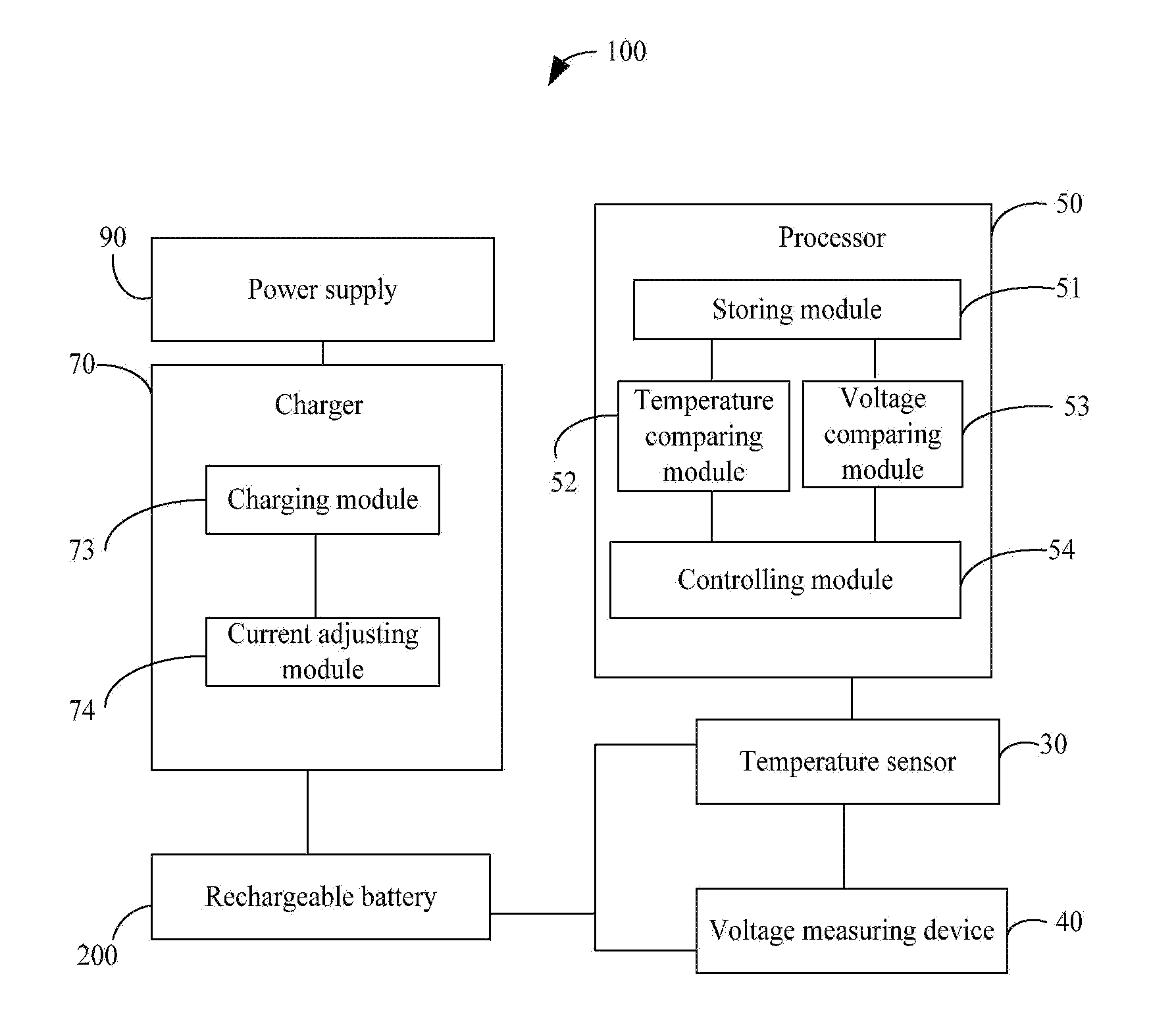
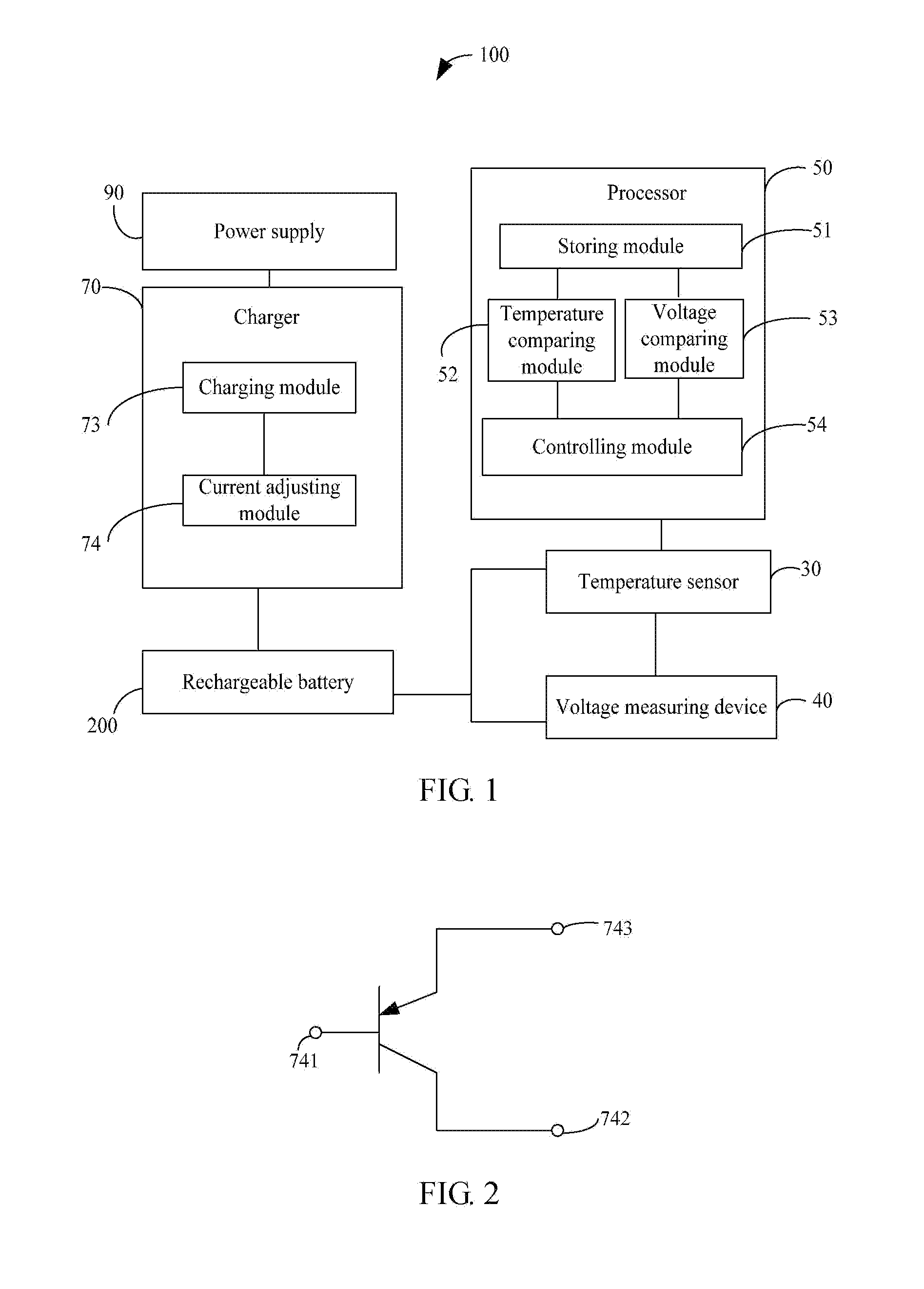
[0012]Referring to FIG. 1 and FIG. 2, a battery charging system 100, according to an exemplary embodiment, is configured for charging a rechargeable battery 200. The battery charging system 100 includes a temperature sensor 30, a voltage measuring device 40, a processor 50, and a charger 70. In the present embodiment, the rechargeable battery 200 is a lithium battery.

[0013]The temperature sensor 30 is positioned on an outer surface of the rechargeable battery 200, and is configured for continuously sensing a current temperature T of the rechargeable battery 200.

[0014]The voltage measuring device 40 is electrically connected to both a positive electrode and a negative electrode of the rechargeable battery 200, and is configured for continuously measuring a current voltage U of the rechargeable battery 200. In the present embodiment, the voltage measuring device 40 is a voltmeter.

[0015]The processor 50 includes a storing module 51, a temperature comparing module 52, a voltage comparin...


PUM


Abstract

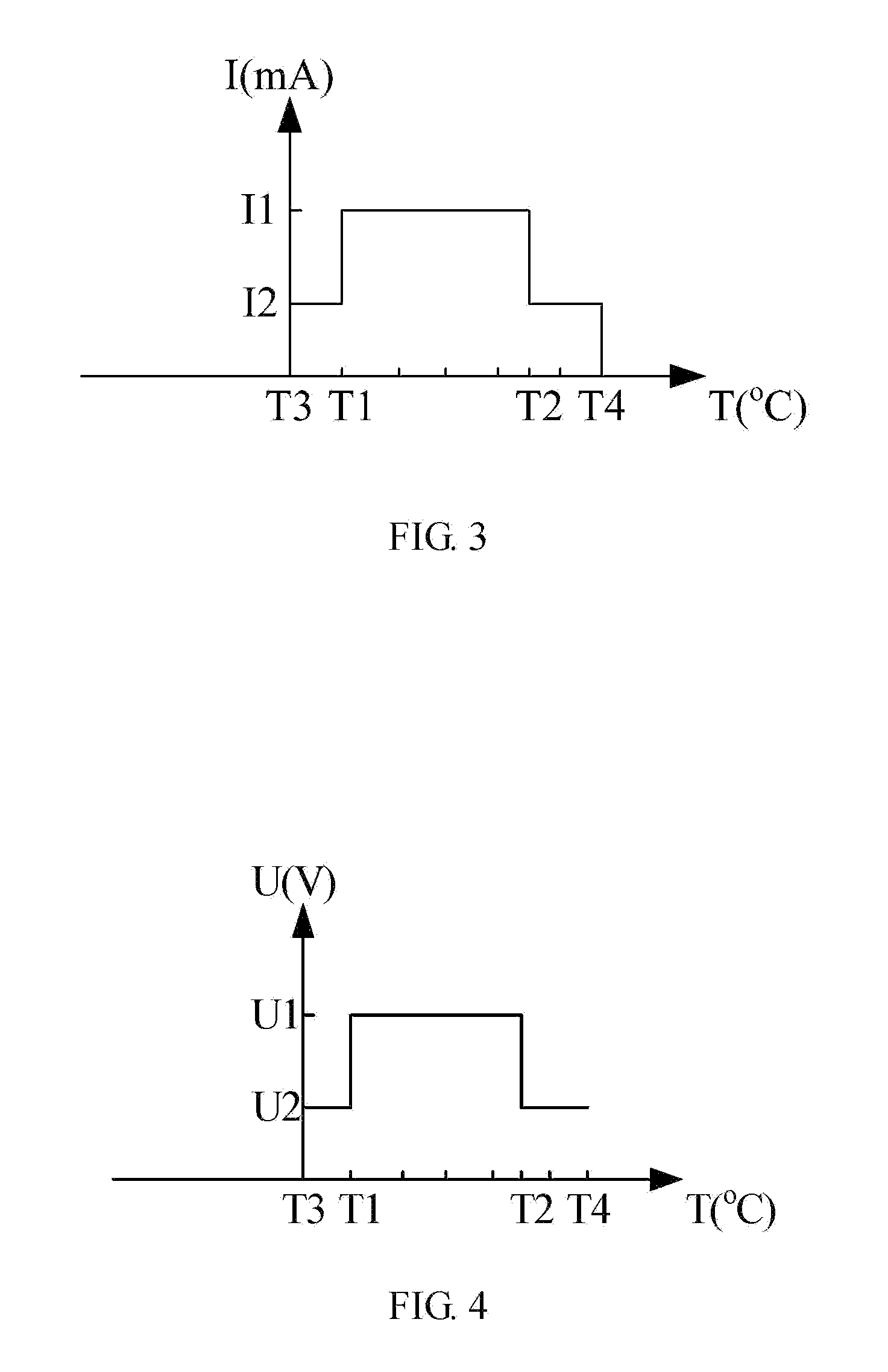
An exemplary battery charging system includes a temperature sensor, a voltage measuring device, a processor and a charger. The temperature sensor is used for continuously sensing the current temperature of a rechargeable battery. The voltage measuring device is used for continuously measuring the current voltage U of the rechargeable battery. The processor is used for comparing the current temperature T with two temperature thresholds and comparing the current voltage U with two cut-off voltages, and generating a PWM control signal to the charger based on the results of the comparisons. The charger is used for charging the battery. When T reads as normal, the charger charges the battery using a first average current I1 and stops charging at U1. When T reads as hot, the charger charges the battery using a second average current I2 and stops charging at U2, wherein I1>I2, U1>U2.

Description

BACKGROUND[0001]1. Technical Field[0002]The present disclosure relates to a battery charging system and method for charging a rechargeable battery.[0003]2. Description of Related Art[0004]The temperature of rechargeable batteries increases quickly during recharging, thus rechargeable batteries are at risk of being damaged when the charging current is too high.[0005]Therefore, it is desirable to provide a battery charging system and method which can overcome the above-mentioned limitations.BRIEF DESCRIPTION OF THE DRAWINGS[0006]Many aspects of the present embodiments will be better understood with reference to the following drawings. The components in the drawings are not necessarily drawn to scale, the emphasis instead being placed upon clearly illustrating the principles of the present embodiments. Moreover, in the drawings, like reference numerals designate corresponding parts throughout the views.[0007]FIG. 1 is a functional block diagram of a battery charging system, according t...

Claims


Application Information

Patent Timeline
IPC IPC(8): H02J7/00
CPCH02J7/00H02J7/007194H02J7/04H02J7/007182H01M10/486H01M10/443
Inventor HUANG, CHUNG-HSIN
Owner HON HAI PRECISION IND CO LTD
Learn More