Electronic glow stick device with alternating flasher

a technology of electric glow sticks and glow sticks, which is applied in semiconductor devices, light sources, lighting and heating apparatus, etc., can solve the problems of not being able to selectively turn off once activated, and not conferring as much safety advantage as flashing lights

Inactive Publication Date: 2011-09-08
DORCY INT
View PDF35 Cites 11 Cited by
  • Summary
  • Abstract
  • Description
  • Claims
  • Application Information

AI Technical Summary

Benefits of technology

[0010]The foregoing and other objects, features and advantages of the invention will become more readily apparent from the f...

Problems solved by technology

One disadvantage of chemical-based glow sticks is that they are unable to selectively turn off once activated other than the slow decay of light output over time once the chemical reaction c...

Method used


Image

  • Electronic glow stick device with alternating flasher
  • Electronic glow stick device with alternating flasher
  • Electronic glow stick device with alternating flasher

Examples


Embodiment Construction

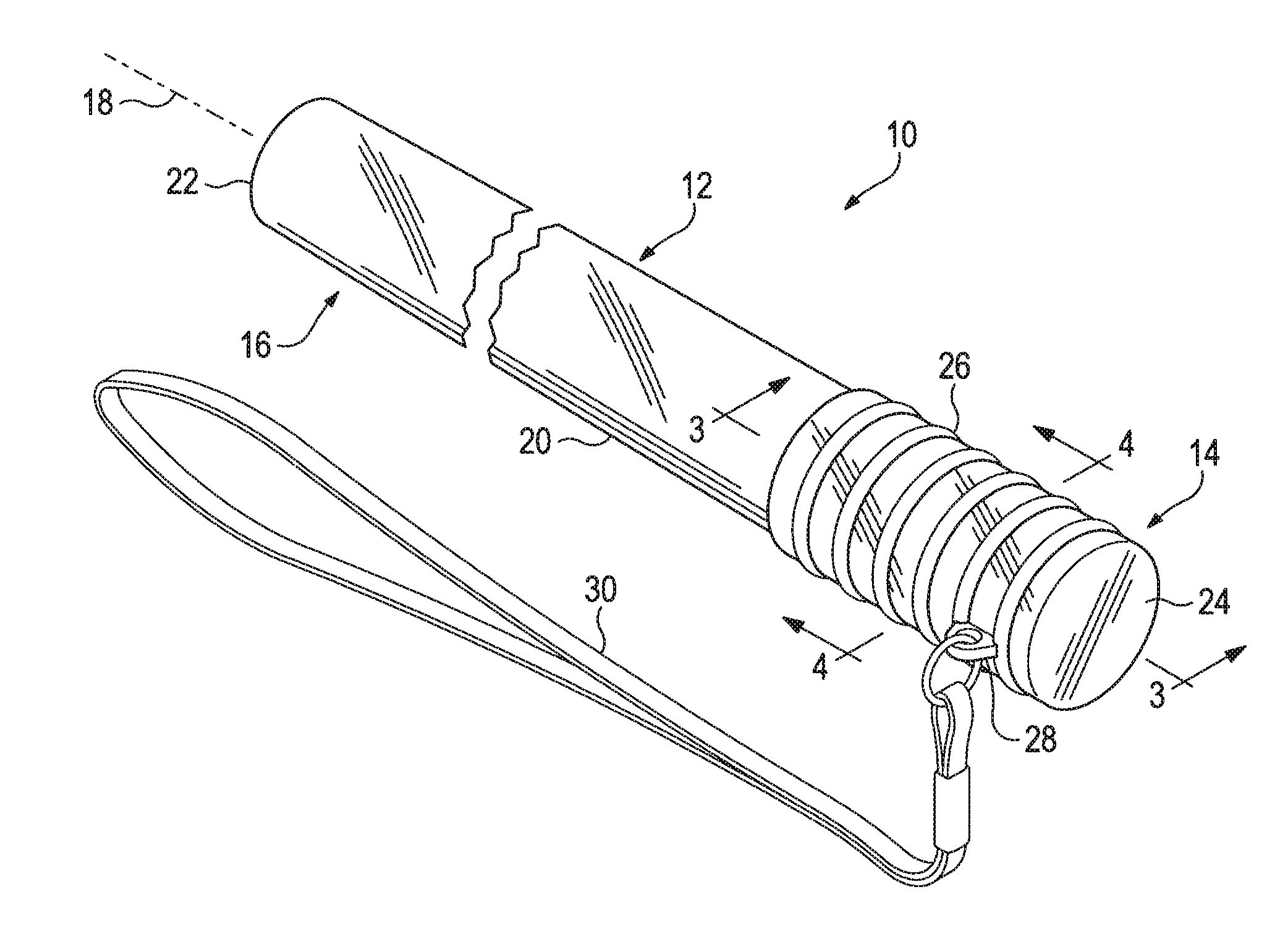
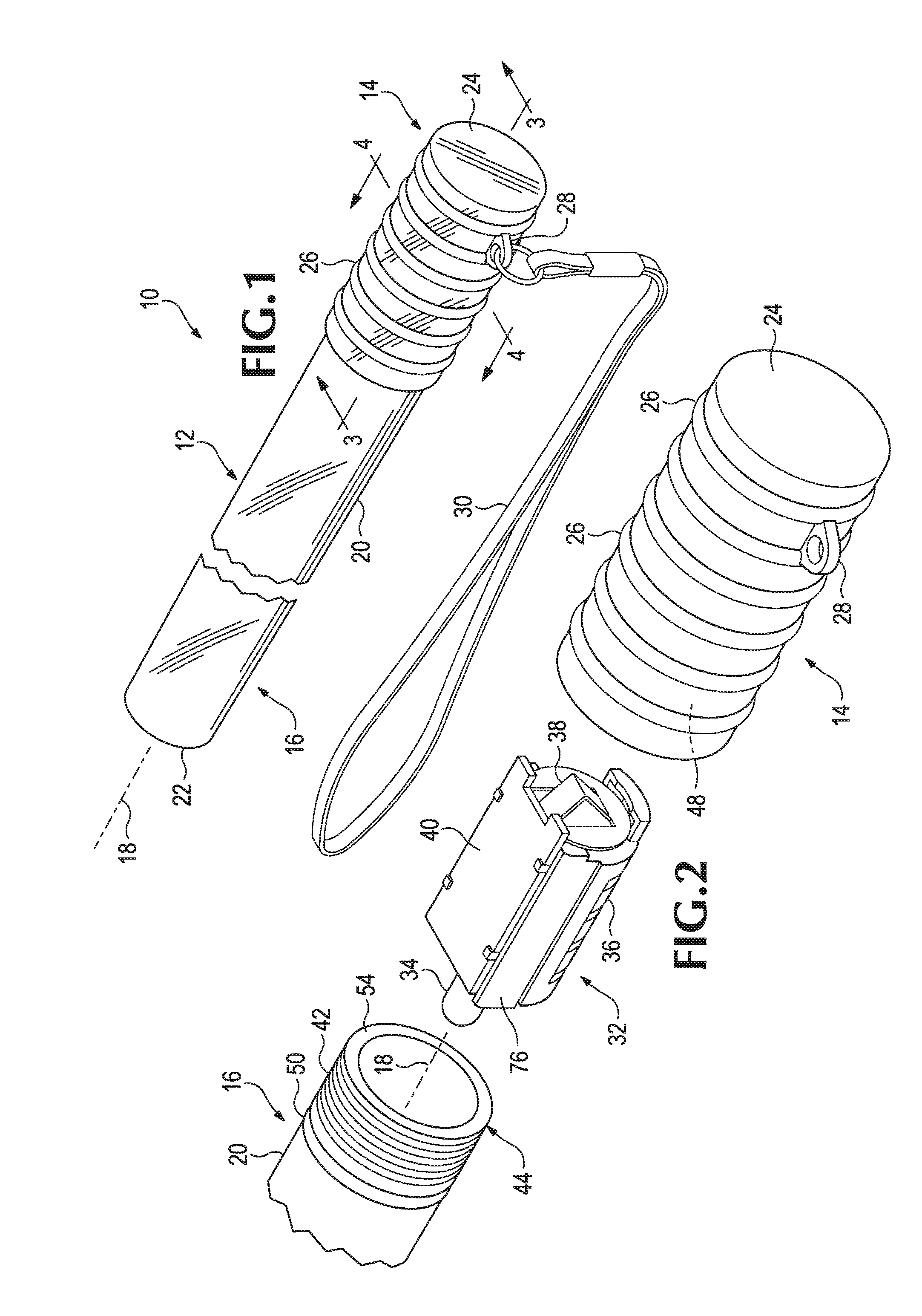
[0019]FIG. 1 illustrates a lighting device 10 implemented according to a preferred embodiment of the invention. Device 10 includes an elongate glowstick housing 12, having an end cap 14 coupled to an illuminated portion 16.

[0020]In the embodiment shown, lighting device 10 has a generally tubular shape extended along a long axis 18 of the device. Illuminated portion 16 includes annular and translucent side walls 20 spaced about the long axis 18 that taper toward a distal end 22. In this fashion, side walls 20 proximal end cap 14 have a first diameter while side walls distal to the end cap have a second diameter, less than the first diameter, so that the side walls move inwardly toward long axis 18 as they extend from the end cap.

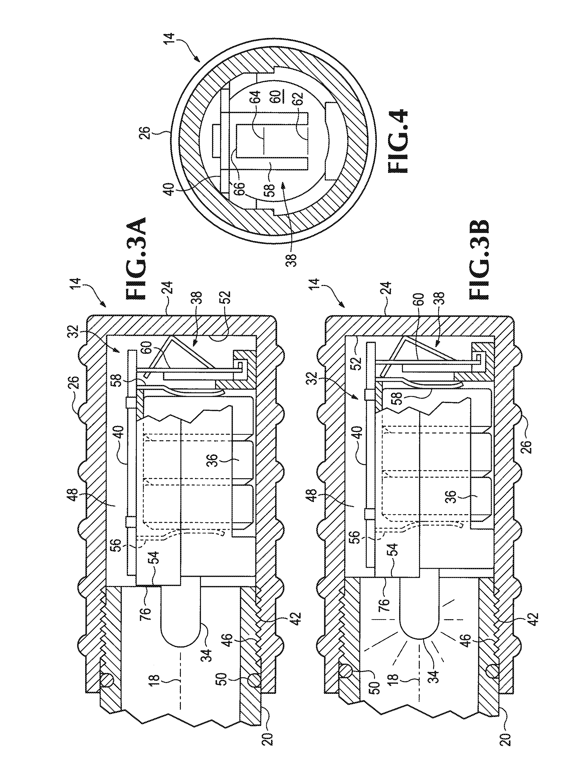
[0021]End cap 14, like illuminated portion 16, includes annular side walls terminating at one end at an outer wall 24, disposed generally perpendicular to the long axis of the device 10, so as to form a hollow cylinder. As will be appreciated from the discuss...


PUM


Abstract

A lighting device including an elongate illuminated portion having translucent side walls spaced about a long axis of the illuminated portion. The device further includes a light source configured to direct light along a length of the illuminated portion and out the translucent side walls. An actuator extends in a biased position oppositely from the light source in a deactivated position. A circuit is electrically coupled between the actuator and light source for activating the light to a first lighting function for so long as the actuator is moved to a compressed position, detecting the actuator being moved back to its biased position, and activating the light to a second lighting function for so long as the actuator is moved back to the compressed position.

Description

BACKGROUND OF THE INVENTION[0001]This invention relates generally to lighting sources and more particularly to a light source with flasher and glow stick function.[0002]Portable lighting is typically designed with the task in mind. Accordingly, flashlights are designed to focus a beam of light for peering into dark corners or cast light longer distances whereas lanterns are designed to cast light short distances but in all directions. One such general lighting source is the chemical-based glow stick. The glow stick embeds two or more chemicals within a hollow plastic tube that, when combined, fluoresce for a brief period of time along the length of the tube. To use the glow stick, the tube is bent so that a capsule containing one of the chemicals is broken. The tube is shaken to mix the two chemicals and start the fluorescence process. Light from this process is radiated out the sidewalls of the tube in all directions.[0003]One disadvantage of chemical-based glow sticks is that they...

Claims


Application Information

Patent Timeline
IPC IPC(8): F21L4/04F21V15/00
CPCF21L4/005F21V15/01F21Y2101/02F21V23/0428F21V23/0407F21Y2115/10
Inventor BERTKEN, DENNIS
Owner DORCY INT
Why Eureka
Try Eureka