
Light emitting diode unit

a technology of light-emitting diodes and led-type devices, which is applied in the manufacture of printed circuits, printed circuit aspects, solid-state devices, etc., can solve the problems of not always constant ratio of fluorescent particles, and achieve the effects of uniform luminance, high light availability, and constant thickness

Inactive Publication Date: 2011-09-15
GIO OPTOELECTRONICS CORP
View PDF7 Cites 1 Cited by
  • Summary
  • Abstract
  • Description
  • Claims
  • Application Information

AI Technical Summary

Benefits of technology

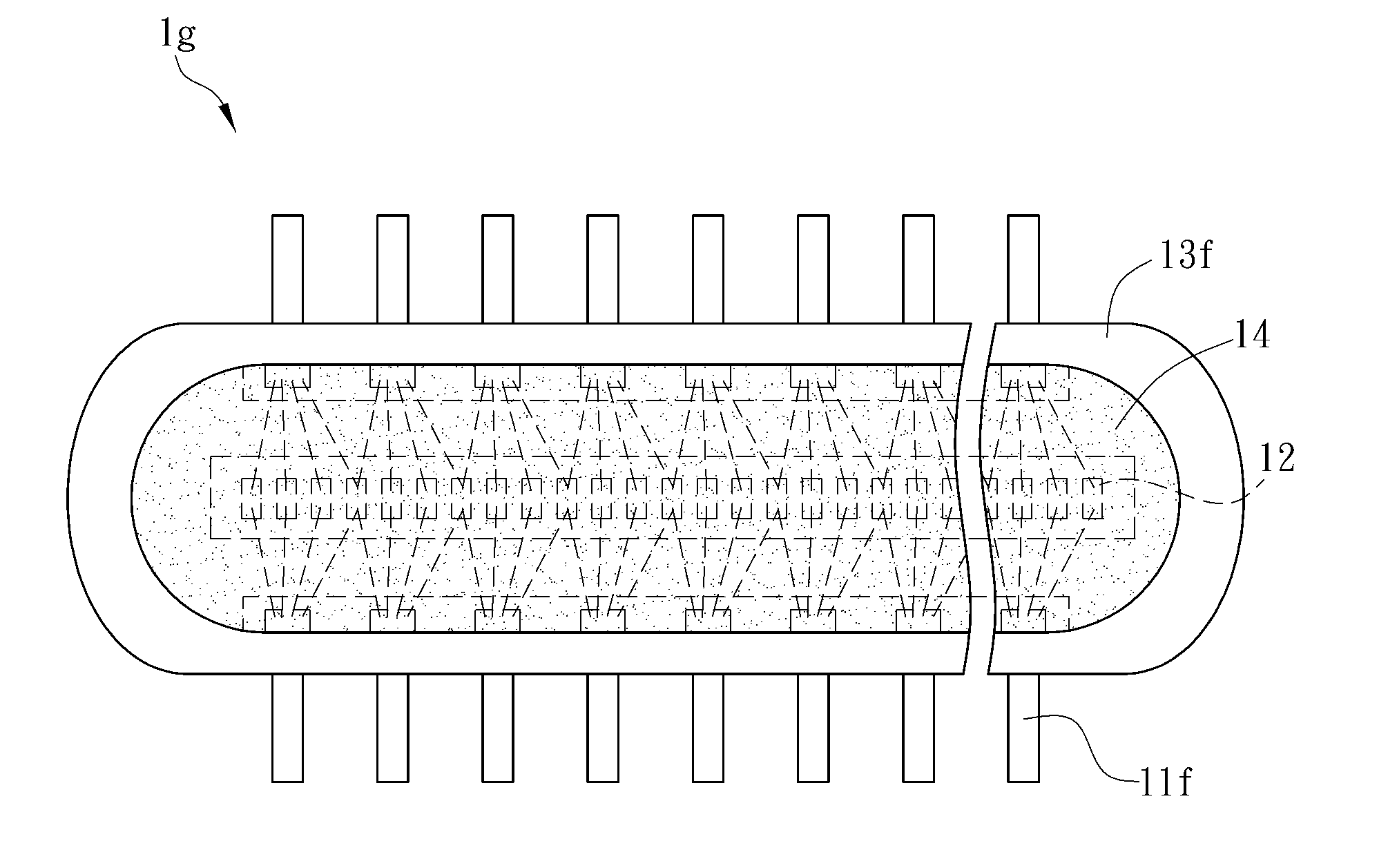
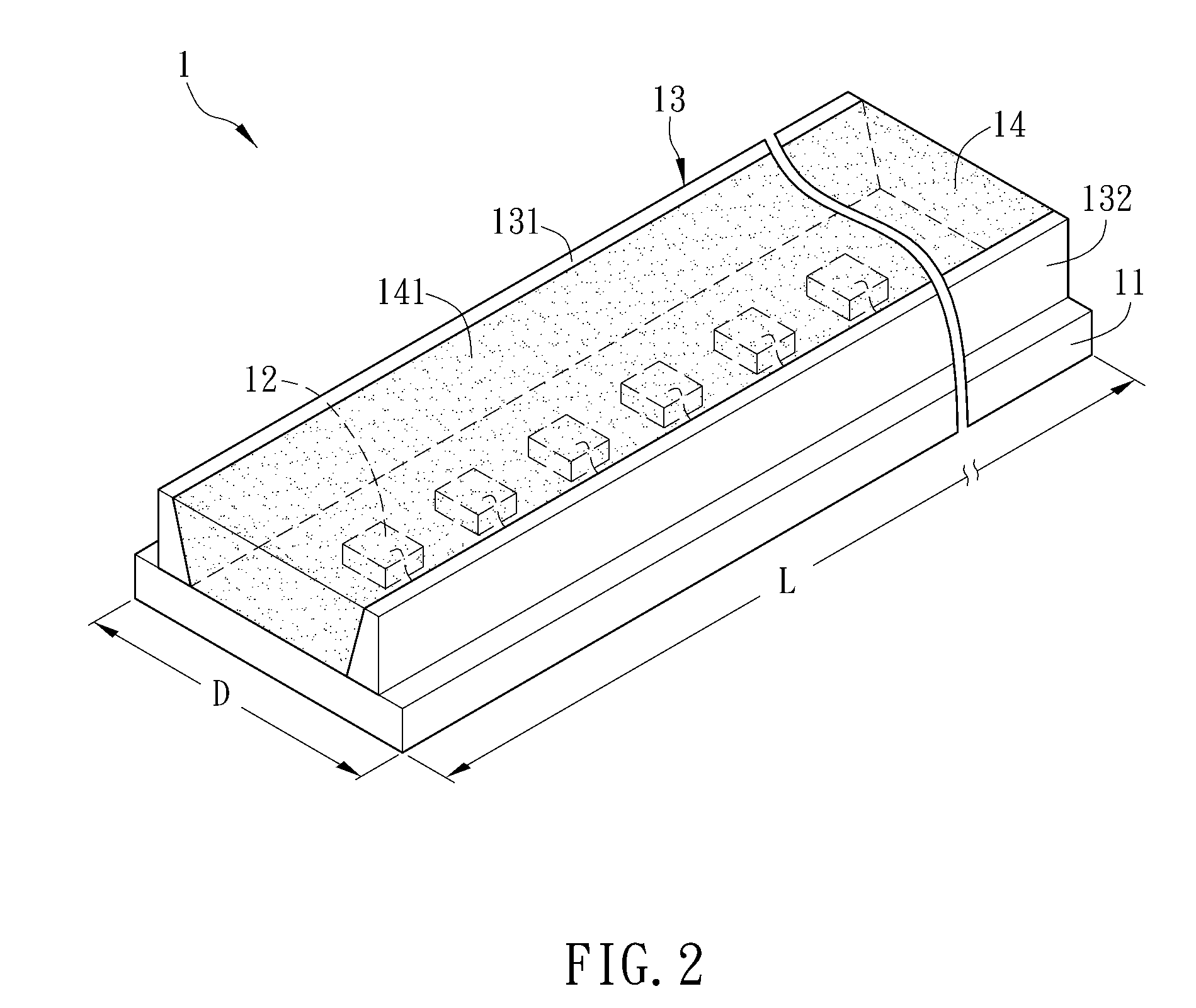
[0010]As mentioned hereinabove, the same molding material covers a plurality of LED dies in the LED unit of the invention, so that the molding material corresponding to each LED die has the substantially constant thickness. The molding material contains the mixed fluorescent particles, and the concentration of the fluorescent particles corresponding to each LED die is also substantially constant, so that the uniform luminance can be obtained. In addition, the LED dies of the invention are disposed along the longitudinal direction of the carrier, and reflecting elements, for reflecting the light outputted from the LED die, are disposed on two sides of the LED die, so that the higher light availability is obtained.

Problems solved by technology

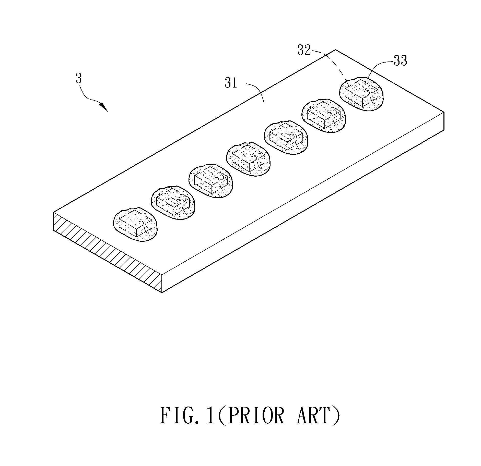
In the dispensing process, however, the fluorescent particles, which are originally suspended in the molding material, may be gradually deposited, and the ratio of the deposited fluorescent particles is not always constant in each dispensing process.

Method used


Image

  • Light emitting diode unit
  • Light emitting diode unit
  • Light emitting diode unit

Examples


Embodiment Construction

[0019]The present invention will be apparent from the following detailed description, which proceeds with reference to the accompanying drawings, wherein the same references relate to the same elements.

[0020]Referring to FIG. 2, a light emitting diode (LED) unit 1 according to a preferred embodiment of the invention includes a carrier 11, a plurality of LED dies 12, a reflecting element 13 and a molding material 14. The LED unit 1 may be a light bar, and may be applied to the fields, such as an illumination device, a lightbox, a backlight module or a display device, wherein the display device includes a flat panel display or an outdoor advertising space.

[0021]The carrier 11 is longitudinal and has a length-width ratio greater than or equal to 5. That is, a length L of the carrier 11 is greater than or equal to five times of a width D of the carrier 11. The carrier 11 may be, for example, a substrate or a lead frame, wherein the substrate may be, for example, a circuit board made of ...


PUM


Abstract

A light emitting diode (LED) unit includes a carrier, a plurality of LED dies, a reflecting element and a molding material. A length-width ratio of the carrier is greater than or equal to 5. The LED dies are disposed on the carrier along a longitudinal direction of the carrier. The reflecting element has two reflecting portions disposed on the carrier along the longitudinal direction. The LED dies are disposed between the reflecting portions. The molding material covers the LED dies and contacts with the reflecting element.

Description

CROSS REFERENCE TO RELATED APPLICATIONS[0001]This Non-provisional application claims priority under 35 U.S.C. §119(a) on Patent Application No(s). 099107201 filed in Taiwan, Republic of China on Mar. 12, 2010, and 099122119 filed in Taiwan, Republic of China on Jul. 6, 2010, the entire contents of which are hereby incorporated by reference.BACKGROUND OF THE INVENTION[0002]1. Field of Invention[0003]The invention relates to a light emitting unit and, in particular, to a light emitting diode (LED) unit.[0004]2. Related Art[0005]A light emitting diode (LED) is a new light emitting source having the advantages of the long lifetime, the small size and the advantage that it cannot be easily broken. The LED is also applied to many products, such as an illuminating apparatus, a backlight module of a flat panel display and the like.[0006]Referring to FIG. 1, a conventional LED unit 3 includes a substrate 31, a plurality of LED dies 32 and a plurality of molding materials 33. The LED dies 32 ...

Claims


Application Information

Patent Timeline
IPC IPC(8): H01L33/60
CPCH01L25/0753H01L33/50H01L33/60H01L2924/09701H05K3/284H01L2924/0002H05K2201/10106H01L2924/00
Inventor PAI, WEI-MING
Owner GIO OPTOELECTRONICS CORP
Learn More