Self-Locking Latch for Window Sash

Inactive Publication Date: 2011-09-15
AMESBURY GROUP
View PDF35 Cites 4 Cited by
  • Summary
  • Abstract
  • Description
  • Claims
  • Application Information

AI Technical Summary

Benefits of technology

[0004]Accordingly, there exists a need for a less complex, cost effective mechanism

Problems solved by technology

As the number of components increases, the associated parts and labor costs may also increas

Method used


Image

  • Self-Locking Latch for Window Sash
  • Self-Locking Latch for Window Sash
  • Self-Locking Latch for Window Sash

Examples


Embodiment Construction

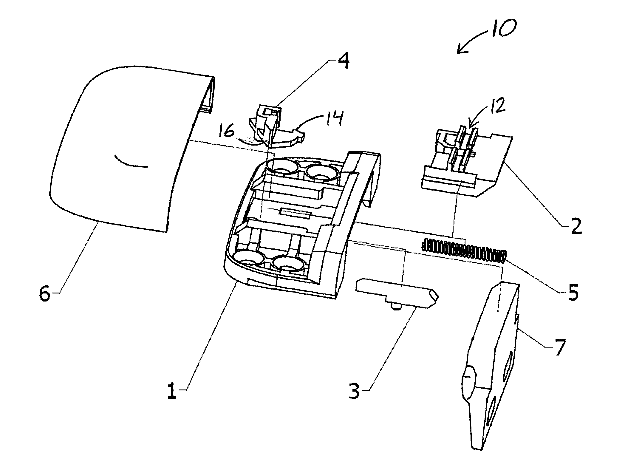
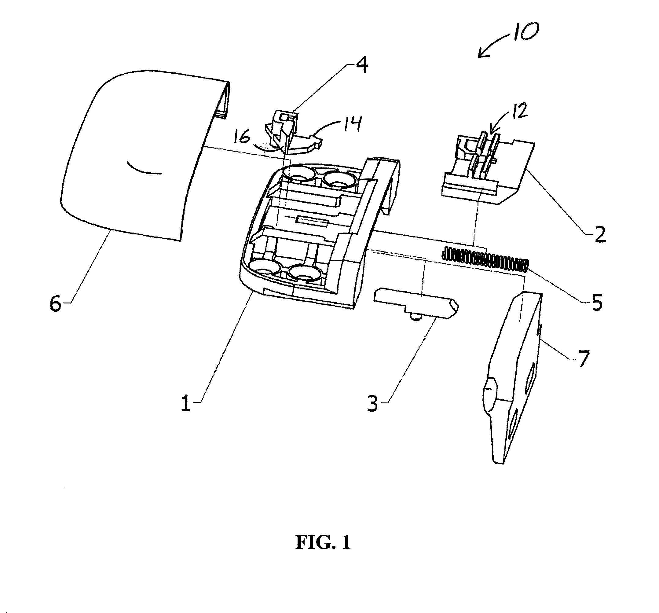
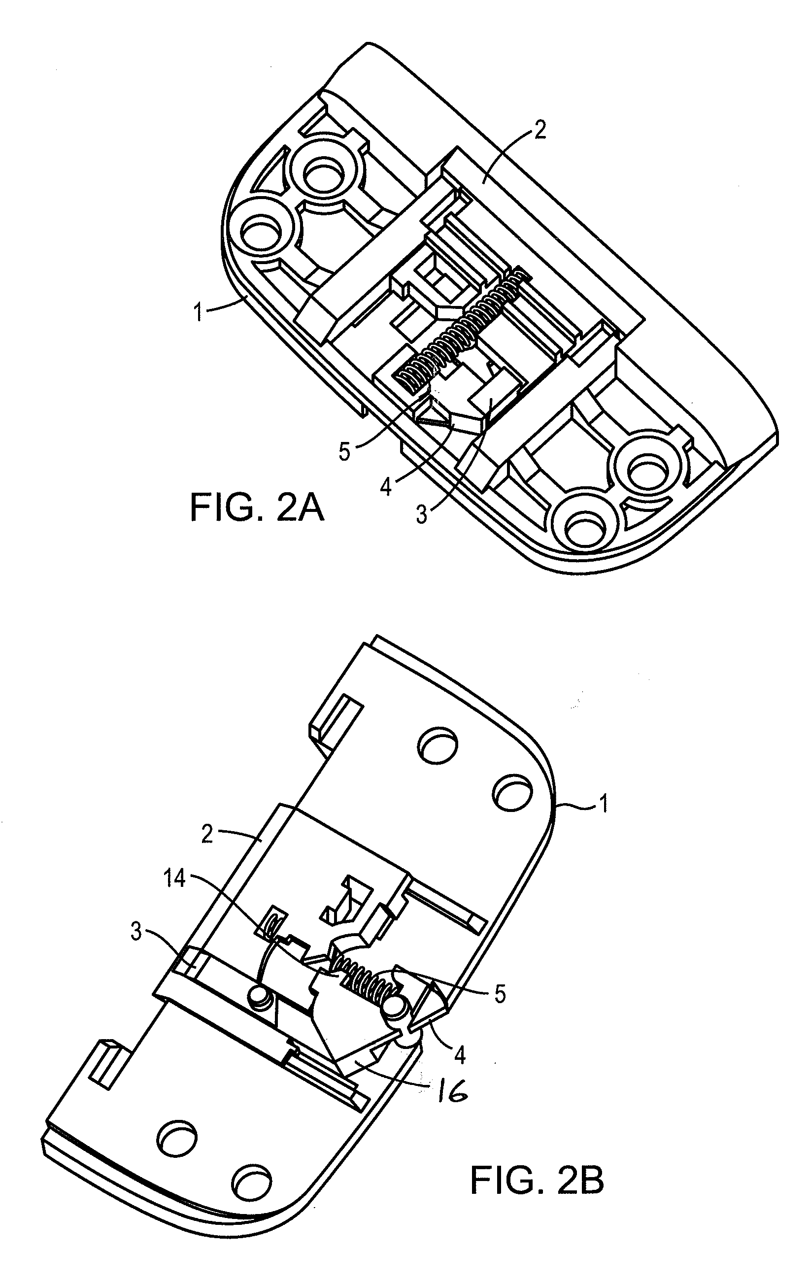
[0025]FIG. 1 depicts various components of a window latch 10. The latch 10 may include a lower housing 1 to act as a base for the various other elements. A tongue 2 may be slidably engaged with the lower housing 1, and may include a channel 12 for engaging a projection on the underside of a cover 6. A trigger 3 may be configured to slide independently of both the lower housing 1 and the tongue 2. A pivotable latch 4 may be pivotally engaged with the lower housing 1 and may include a hook 14 to engage a structure on the underside of the tongue 2 when the tongue 2 is in a retracted position, as well as an arm 16, as described in greater detail below. The spring 5 may simultaneously bias the tongue 2 in an extended position and the latch 4 in a latched position. The cover 6 may substantially cover and surround the lower housing 1 and the other internal components of the latch 10 and may be used to move the tongue 2 from the extended position to the retracted position. In other embodime...


PUM


Abstract

A window latch for a double hung window includes a housing and a tongue slidably engaged with the housing for moving between a retracted position and an extended position. A pivotable latch pivotably mounted within the housing releasably retains the tongue in the retracted position. As a window sash of the double hung window is lifted, a trigger slidably engaged with the housing pivots the pivotable latch so as to release the tongue from the retracted position.

Description

PRIORITY CLAIM[0001]This application claims priority to and the benefit of U.S. Provisional Patent Application Ser. No. 61 / 312,001, filed on Mar. 9, 2010, the disclosure of which is hereby incorporated herein by reference in its entirety.TECHNICAL FIELD[0002]This application relates to latches for windows and, more particularly, to self-locking latches for sliding window systems.BACKGROUND[0003]A number of self-locking window latches are available on the market today. These include the model 4748 latch from Amesbury Group, Inc. (Amesbury, Mass.), the Prolatch latch from Interlock USA, Inc. (Reno, Nev.), the Autolock latch from Milgard Manufacturing, Inc. (Tacoma, Wash.), the I-Lock latch from Roto Frank AG (Leinfelden-Echterdingen, Germany), and the 19 Series Positive Action Lock latch from Truth Hardware (Owatonna, Minn.). Additionally, the Prolatch latch appears to be further described in U.S. Pat. No. 7,407,199, the disclosure of which is hereby incorporated by reference herein i...

Claims


Application Information

Patent Timeline
IPC IPC(8): E05C5/02E05B15/02E05C1/02
CPCE05C1/10E05B63/20Y10T292/0887Y10T292/1014
Inventor WERON, CORBYCLARK, GAVIN
Owner AMESBURY GROUP
Why Eureka
Try Eureka