Detection of Movement of a Stationary Video Camera

a video camera and motion detection technology, applied in the field of video surveillance systems, can solve the problems of adversely affecting the efficiency of such systems, affecting the algorithm being used to automatically, and the deliberate or unintentional redirection of the camera

Inactive Publication Date: 2011-09-15
TEXAS INSTR INC
View PDF13 Cites 22 Cited by
  • Summary
  • Abstract
  • Description
  • Claims
  • Application Information

AI Technical Summary

Problems solved by technology

Obviously the efficacy of such systems is adversely affected by tampering with one or more of the cameras.
For example, a camera may be deliberately or unintentionally redirected, i.e., moved, to point awa...

Method used


Image

  • Detection of Movement of a Stationary Video Camera
  • Detection of Movement of a Stationary Video Camera
  • Detection of Movement of a Stationary Video Camera

Examples


Embodiment Construction

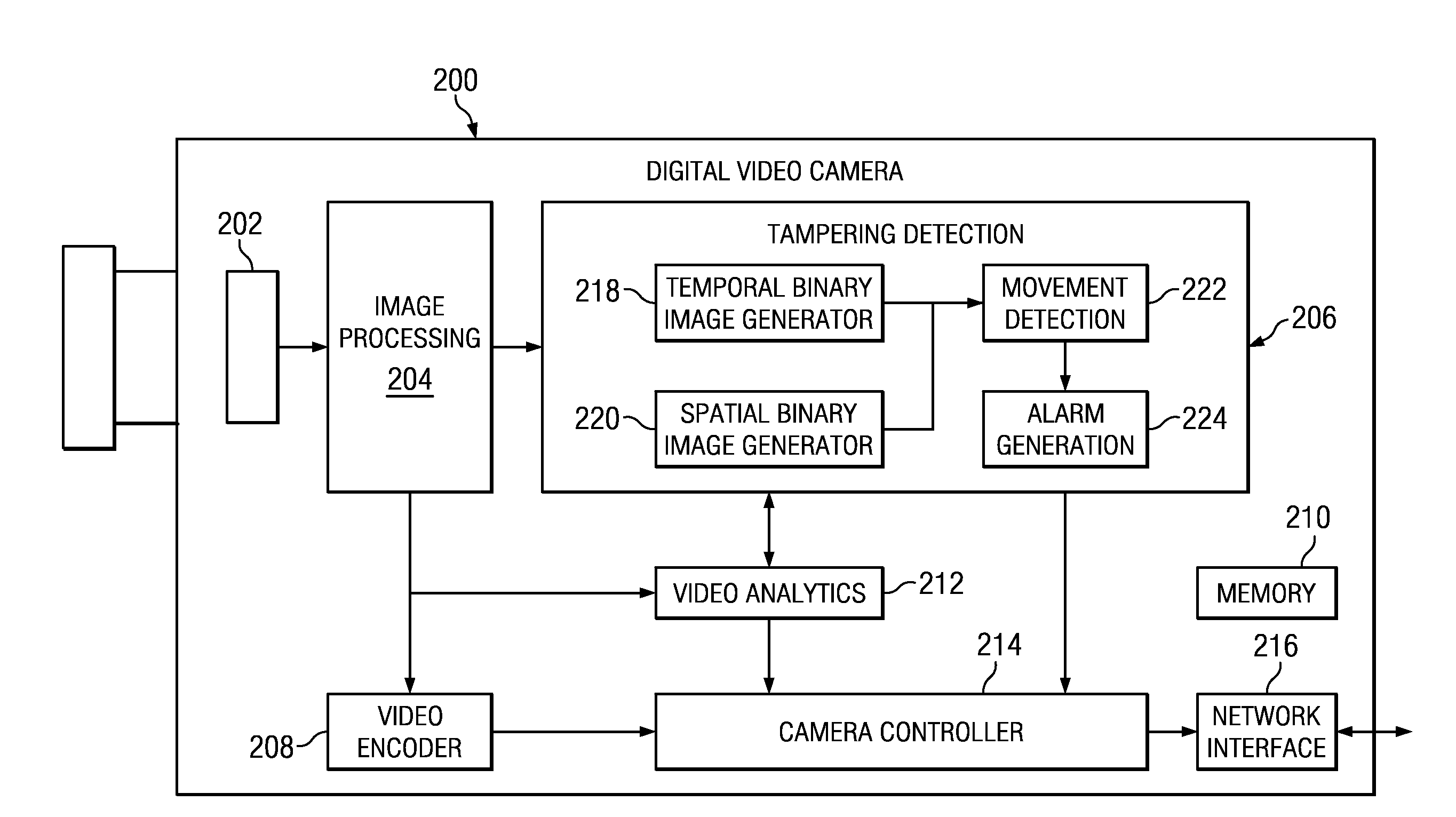
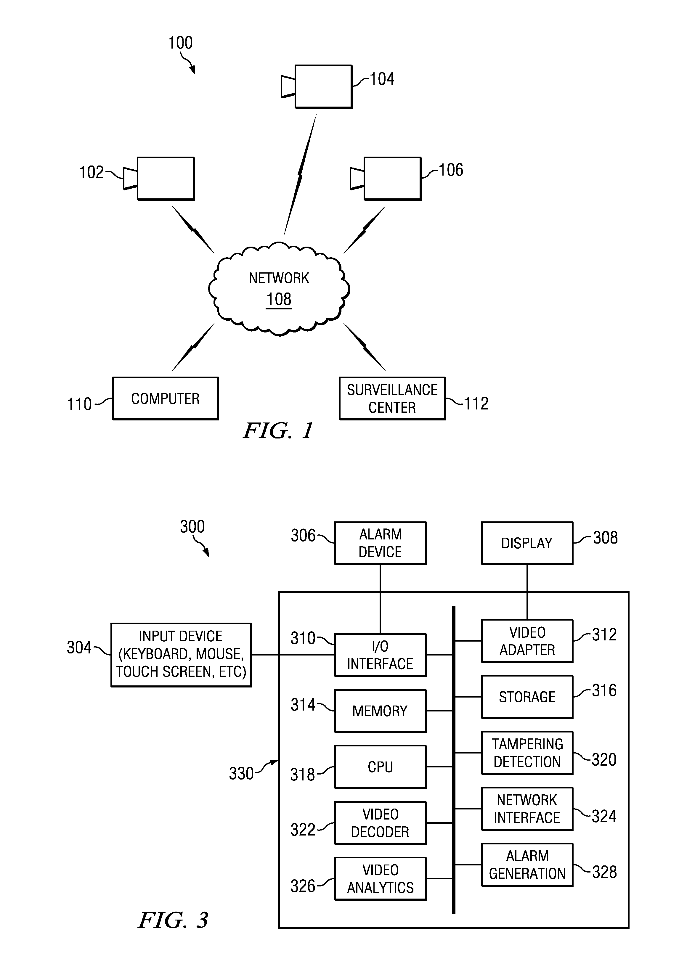
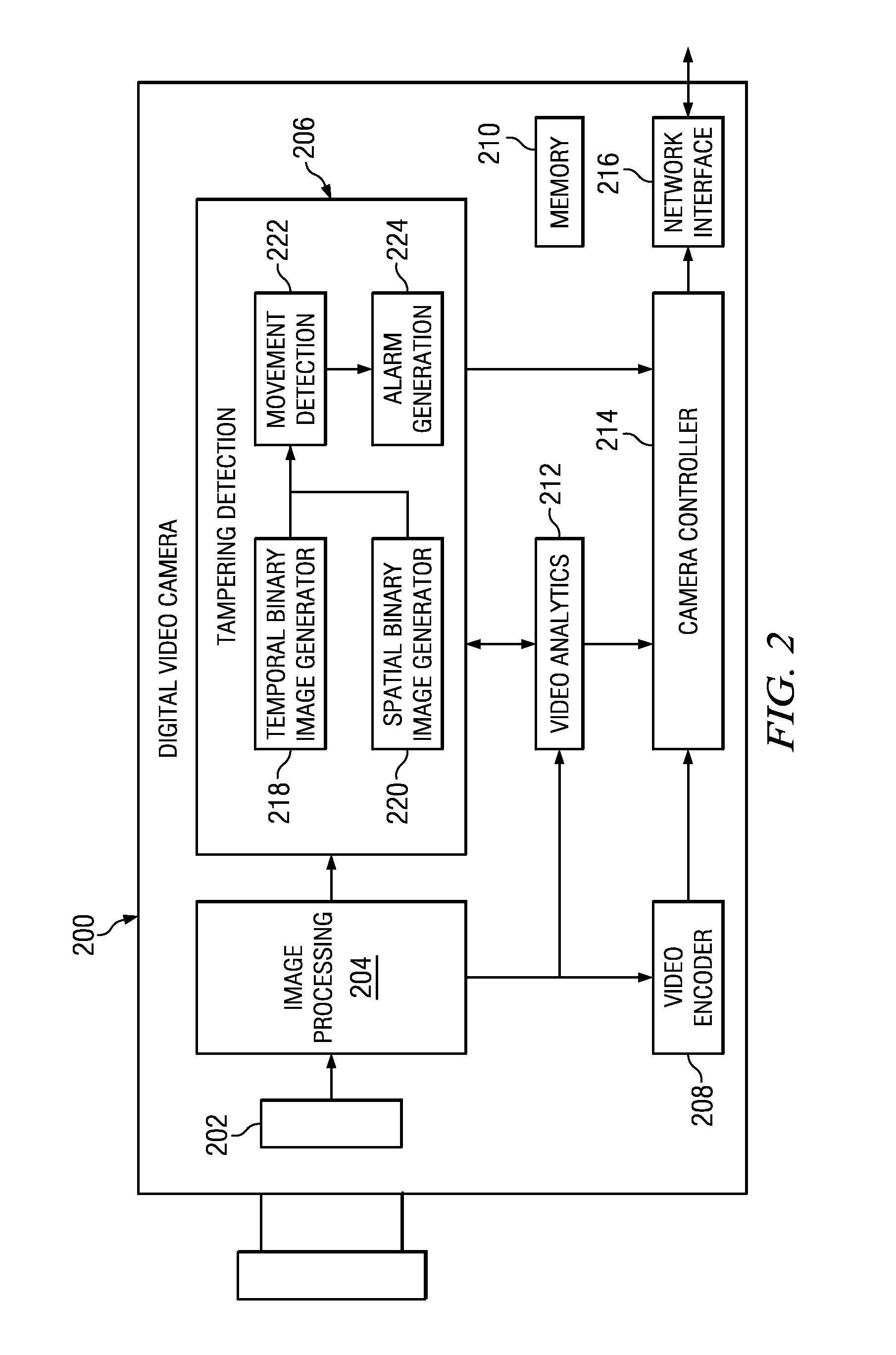
[0009]Specific embodiments of the invention will now be described in detail with reference to the accompanying figures. Like elements in the various figures are denoted by like reference numerals for consistency.

[0010]Certain terms are used throughout the following description and the claims to refer to particular system components. As one skilled in the art will appreciate, components in digital systems may be referred to by different names and / or may be combined in ways not shown herein without departing from the described functionality. This document does not intend to distinguish between components that differ in name but not function. In the following discussion and in the claims, the terms “including” and “comprising” are used in an open-ended fashion, and thus should be interpreted to mean “including, but not limited to . . . .” Also, the term “couple” and derivatives thereof are intended to mean an indirect, direct, optical, and / or wireless electrical connection. Thus, if a ...


PUM


Abstract

A method of detecting movement of a video camera is provided that includes computing a reference spatial derivative image from a reference frame, computing a temporal derivative image based on two frames of a video sequence captured by the video camera, and determining whether the video camera has moved based on the number of pixels in the temporal derivative image that match pixels in the reference spatial derivative image.

Description

CROSS-REFERENCE TO RELATED APPLICATIONS[0001]This application claims benefit of U.S. Provisional Patent Application Ser. No. 61 / 312,290, filed Mar. 10, 2010, which is incorporated by reference herein in its entirety.BACKGROUND OF THE INVENTION[0002]Many video surveillance systems may use stationary video cameras, i.e., cameras that are fixed in place and not intended to move, to provide fixed stationary views of areas of interest. Obviously the efficacy of such systems is adversely affected by tampering with one or more of the cameras. For example, a camera may be deliberately or unintentionally redirected, i.e., moved, to point away from the area of interest and become of limited use for monitoring the area of interest. Further, the movement may adversely affect any algorithms being used to automatically analyze the video from the camera. Accordingly, detection of movement of a stationary camera is important.BRIEF DESCRIPTION OF THE DRAWINGS[0003]Particular embodiments in accordanc...

Claims


Application Information

Patent Timeline
IPC IPC(8): H04N7/18
CPCH04N7/188
Inventor SHARMA, VINAY
Owner TEXAS INSTR INC
Why Eureka
Try Eureka