Method and system for playing back an audio signal

a multi-channel audio and audio signal technology, applied in the direction of loudspeaker spatial/constructional arrangement, stereophonic arrangment, electrical equipment, etc., to achieve the effect of better control, better control over the directivity of sound sources, and better control of sound playback accuracy

Active Publication Date: 2015-09-10
SENNHEISER ELECTRONICS GMBH & CO KG
View PDF1 Cites 14 Cited by
  • Summary
  • Abstract
  • Description
  • Claims
  • Application Information

AI Technical Summary

Benefits of technology

[0069]In general, creating virtual sources makes it possible to obtain better control and better accuracy in the sound playback of an audio signal than when using “direct” sound playback (i.e. without spatial filtering) via the loudspeakers of the playback device, since that is limited to the sole capacity of the loudspeakers of the playback device. Creating virtual sources makes it possible to have better control over the directivity of the sound sources as reconstituted.
[0070]Furthermore, using beamforming to create a virtual source inside or outside the playback window makes it easy to control the width of the virtual source as created in this way. Beamforming is particularly well adapted to playing back signals via dense loudspeaker networks (e.g. a

Problems solved by technology

Although Document WO 2012/025580 performs spatial analysis and playback of the multichannel audio signal while taking account of the distribution of the loudspeakers of the playback device, in particular by means of the concept of the sound playback window, it is nevertheless restricted to use with playback devices having loudspeakers that are spread throughout the room in which the signal is to be played back and for playback in an extended listening zone.
However Document WO 2012/025580 does not specifically address playing back a multi

Method used


Image

  • Method and system for playing back an audio signal
  • Method and system for playing back an audio signal
  • Method and system for playing back an audio signal

Examples


example 1

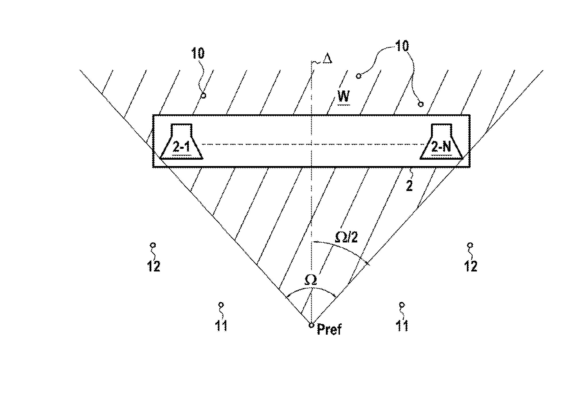
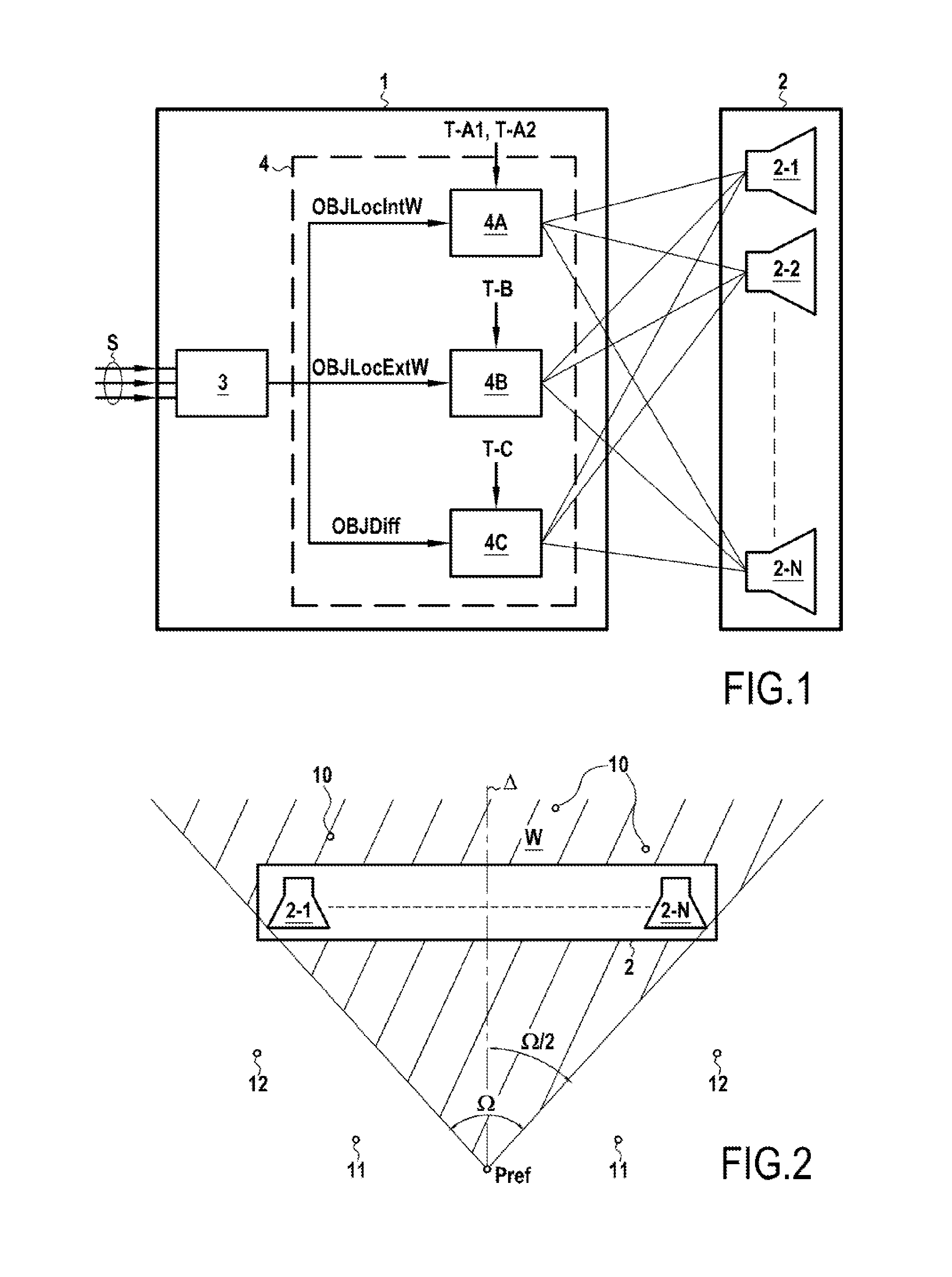
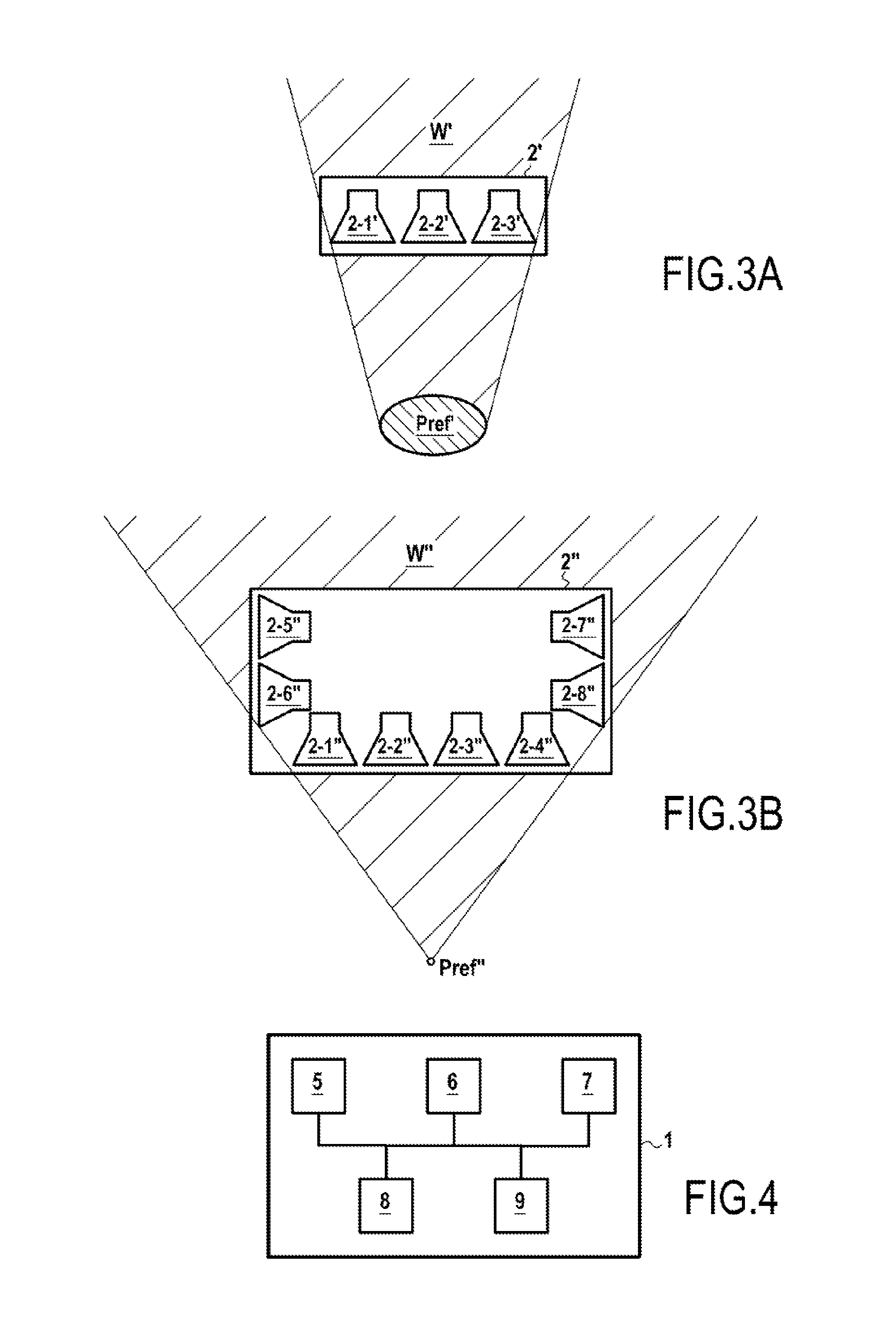
[0209]In this first example, it is assumed that the playback device 2 is an acoustic enclosure of the horizontal soundbar type having three loudspeakers 2-1, 2-2, and 2-3 (a central loudspeaker and two lateral loudspeakers).

[0210]The position Pref is selected to be a point, centered relative to the playback device 2.

[0211]It is also assumed that the multichannel signal S delivered to the playback system 1 during the step E10 is a stereo audio signal, in other words is a signal made up of two distinct channels.

[0212]In this first example, the following steps are performed by the playback system 1 on the signal S:

[0213]1) Decomposing the signal S into frequency sub-bands in step E30 with the help of a Fourier transform applied to the signal S, each frequency sub-band comprising a signal Si that is itself made up of two channels.

[0214]2) Spatially analyzing ΣI the signal S, or in equivalent manner each signal Si in each frequency sub-band, by performing time analysis of the signal Si d...

example 2

[0228]In this second example, it is assumed that the playback device 2 is a compact acoustic enclosure of the horizontal soundbar type having 15 loudspeakers 2-1, 2-2, . . . , 2-15 and having a length of about 1 m.

[0229]The position Pref is selected to be a point that is centered relative to the playback device 2.

[0230]It is also assumed that the multichannel signal S delivered to the playback system 1 during step E10 is a 5.1 audio signal. Such a signal already contains spatialization information intrinsically. More specifically, the ITU-R BS.775-1 standard defining the format of 5.1 signals assumes a center situated at 0°, left and right channels L and R situated at ±30° relative to the center, and rear left and rear right channels Ls and Rs situated at ±110° relative to the center.

[0231]In this second example, the following steps are performed by the playback system 1 on the basis of the signal S:

[0232]1) Decomposing the signal S into frequency sub-bands in step E20 using a Fouri...

example 3

[0250]In this third example, it is assumed that the playback device 2 is a compact acoustic enclosure having eight loudspeakers 2-1, 2-2, . . . , 2-8, and having a width of about 80 cm, with four front loudspeakers 2-1, . . . , 2-4, and two respective pairs of loudspeakers 2-5&2-6 and 2-7&2-8 situated on opposite sides of the device 2 (device similar to device 2″ shown in FIG. 3B).

[0251]The position Pref is selected to be a point, centered relative to the playback device 2.

[0252]It is also assumed that the multichannel signal S delivers to the playback system 1 during the step E10 is an audio signal made up of four distinct channels.

[0253]In this third example, the following steps are performed by the playback system 1 on the signal S:

[0254]1) Decomposing the signal S into frequency sub-bands in step E20 using a Fourier transform applied to the signal S, each frequency sub-band comprising a signal Si made up of four channels.

[0255]2) Spatially analyzing ΣI the signal S, or in equiva...


PUM


Abstract

The method of playing back a multichannel audio signal via a playback device comprises a plurality of loudspeakers arranged at fixed locations of the device and define a spatial window for sound playback relative to a reference spatial position. The method comprises for at least one sound object extracted from the signal, estimating a diffuse or localized nature of the object and estimating its position relative to the window. The audio signal is played back via the loudspeakers of the device during which playback treatment is applied to each sound object for playing back via at least one loudspeaker of the device, which treatment depends on the diffuse or localized nature of the object and on its position relative to the window, and includes creating at least one virtual source outside the window from loudspeakers of the device when the object is estimated as being diffuse or positioned outside the window.

Description

BACKGROUND OF THE INVENTION[0001]The invention relates to the general field of acoustic treatments and sound spatialization.[0002]The invention relates more particularly to playing back a multichannel audio signal via a determined playback device that has a plurality of loudspeakers arranged at fixed locations of the playback device.[0003]The invention applies in preferred but non-limiting manner to a playback device of the acoustic enclosure type, also known as a “baffle structure”. In known manner, such an acoustic enclosure is constituted by a single or one-piece structure incorporating the various loudspeakers that are used for playing back the audio signal (the loudspeakers are not separable from the enclosure). An example acoustic enclosure is in particular a soundbar in which the various loudspeakers are incorporated.[0004]The present invention also presents a particular advantage when it is applied to a so-called “compact” acoustic enclosure or more generally to a compact pl...

Claims


Application Information

Patent Timeline
IPC IPC(8): H04S7/00
CPCH04S7/30H04S3/00H04S2420/13
Inventor NGUYEN, KHOA-VANCORTEEL, ETIENNE
Owner SENNHEISER ELECTRONICS GMBH & CO KG
Why Eureka
Try Eureka