Wireless communication device

a communication device and wireless technology, applied in the field of wireless communication devices, can solve the problems of carrier frequency difference and reception characteristics deterioration, and achieve the effect of simple configuration

Active Publication Date: 2012-08-14
INTERDIGITAL PATENT HLDG INC
View PDF19 Cites 13 Cited by
  • Summary
  • Abstract
  • Description
  • Claims
  • Application Information

AI Technical Summary

Benefits of technology

[0025]According to the present invention, by preparing in advance a reference signal matching a received spatial-multiplex pilot subcarrier signal and comparing at the phase compensating section the reference signal with a spatial-multiplex pilot subcarrier signal actually received, the phase difference of the spatial-multiplex pilot subcarrier signal actually received is detected and the phase difference is compensated for, so that phase difference detection and phase compensation can be carried out even in a case where pilot subcarrier signals are spatial-multiplexed and transmitted, with a simple configuration.

Problems solved by technology

When M-ary value QAM is used to modulate subcarriers, data decision is carried out upon demodulation with the absolute phase as a reference using a detection circuit, and so the residual carrier frequency difference remains or detection error occurs upon phase rotation due to phase noise and therefore reception characteristics deteriorate.

Method used


Image

  • Wireless communication device
  • Wireless communication device
  • Wireless communication device

Examples


embodiment 1

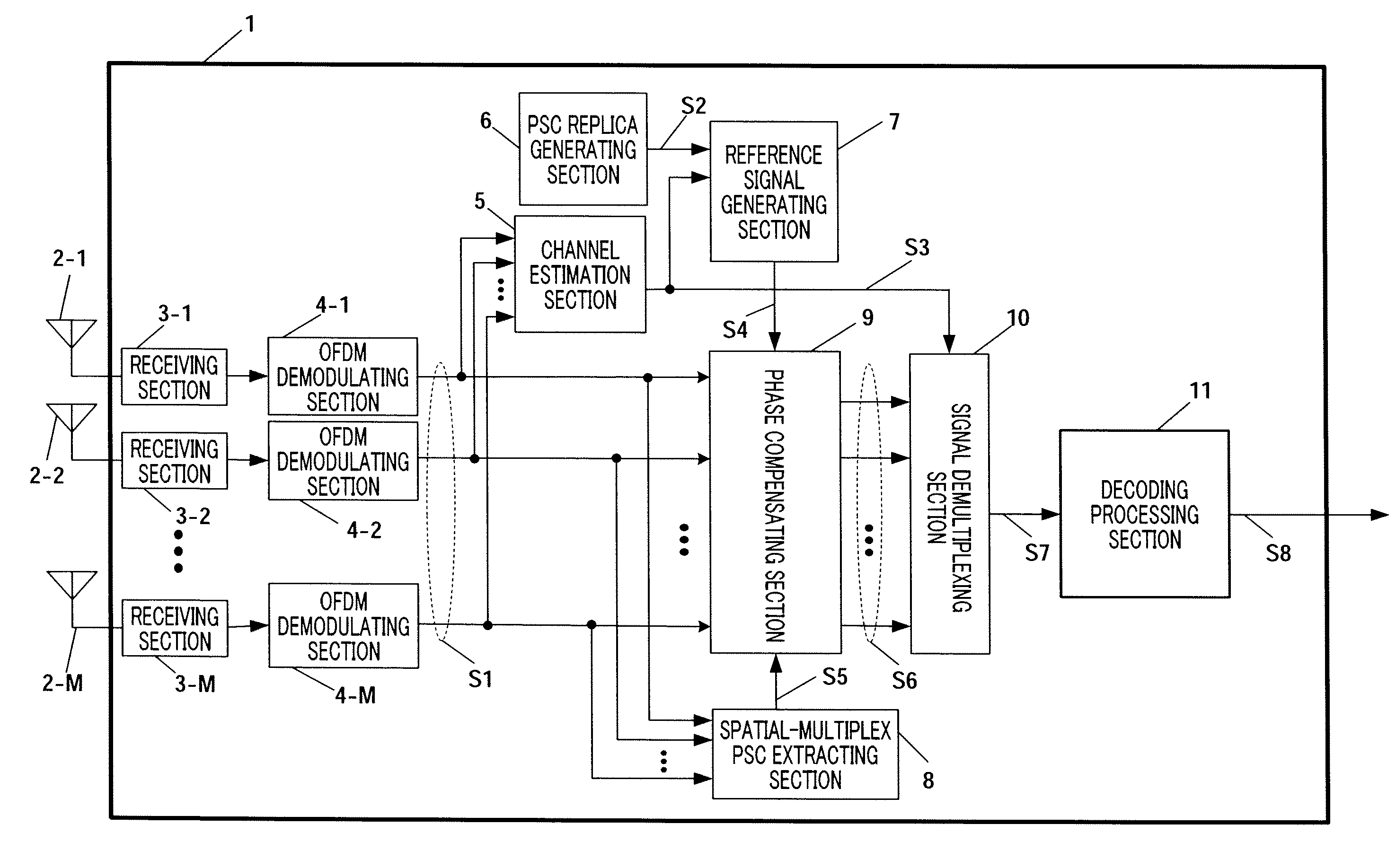
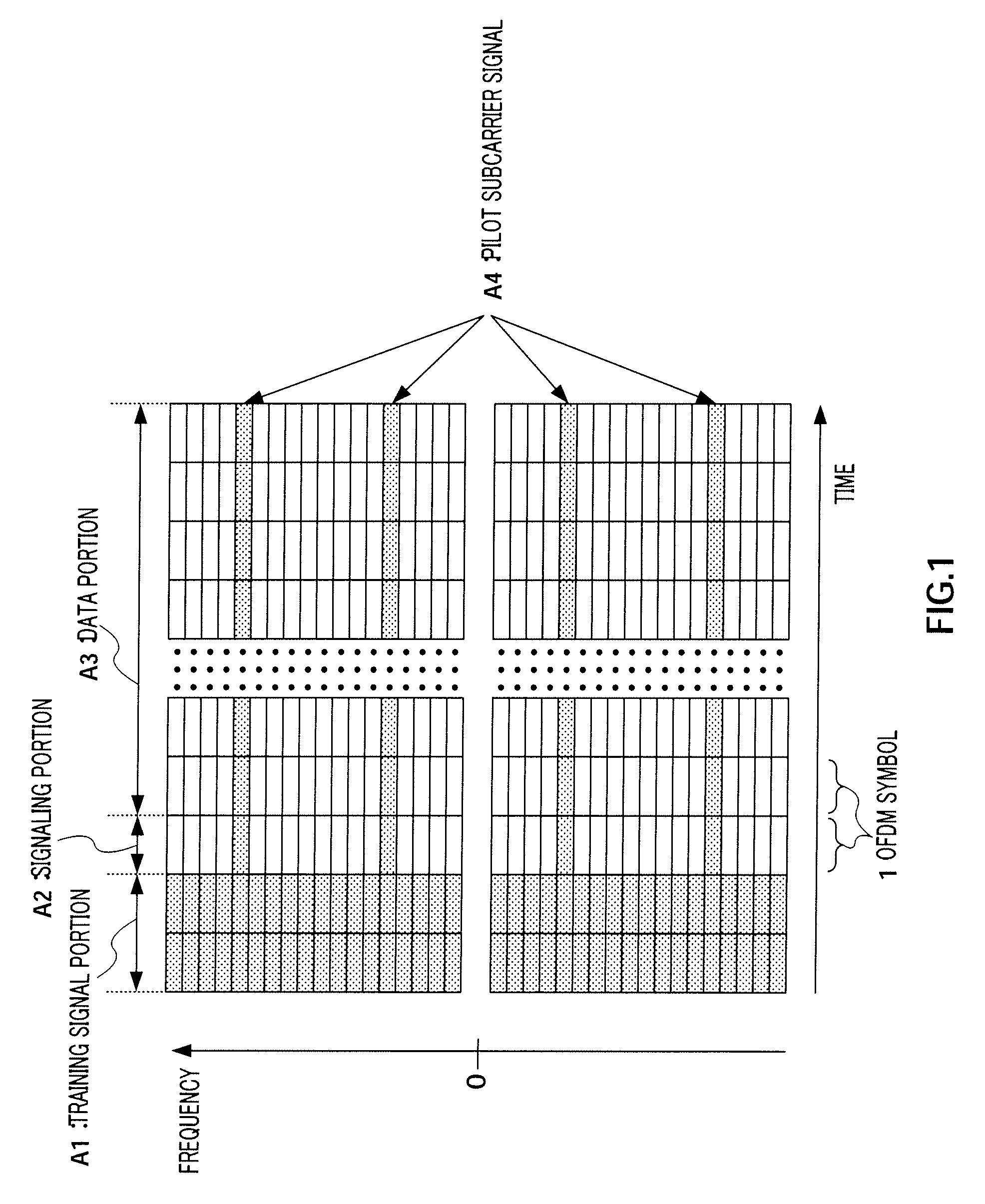
[0045]FIG. 3 shows a configuration of wireless communication apparatus 1 according to Embodiment 1 of the present invention. With the present embodiment, a configuration of receiving sections of wireless communication apparatus 1 using OFDM as a multicarrier transmission scheme will be described. Further, OFDM modulation and OFDM demodulation are known techniques disclosed in, for example, the document “OFDM system technique and MATLAB simulation explanation,” Ochi, published by TRICEPS, and the detailed explanation will be omitted. Further, wireless communication apparatus 1 shows only a configuration of the receiving system and a configuration of the transmitting system is not shown. Further, the following description assumes packet transmission used in, for example, the wireless LAN. FIG. 4 shows a configuration example of a packet.

[0046]In FIG. 4, a packet is configured with training signal portion 20 configured with a known signal sequence, signaling portion 21 and data portion...

embodiment 2

[0094]FIG. 6 show a configuration of the wireless communication apparatus according to Embodiment 2, and, in FIG. 6, the same components as in FIG. 3 are assigned the same reference numerals. Similar to FIG. 3, FIG. 6 shows only a configuration for reception in wireless communication apparatus 1b, and the illustration of the configuration for transmission is omitted.

[0095]Wireless communication apparatus 1b of the present embodiment differs from Embodiment 1 in having interference cancellation PSC phase compensating section 40 subsequent to phase compensating section 9.

[0096]Interference cancellation PSC phase compensating section 40 receives inputs of subcarrier signal Z (m, fs) (S6 in FIG. 6) in which the phase rotation is compensated for by phase compensating section 9 and which is represented by equation 10, pilot subcarrier replica signal S2 outputted from PSC replica generating section 6 and channel estimation signal S3 outputted from channel estimation section 5, and removes ...

embodiment 3

[0119]FIG. 9 shows a configuration of the wireless communication apparatus according to Embodiment 3, and, in FIG. 9, the same components as in FIG. 3 are assigned the same reference numerals. Similar to FIG. 3, FIG. 9 shows only a configuration for reception in wireless communication apparatus 1d, and the illustration of the configuration for transmission is omitted.

[0120]Wireless communication apparatus 1d of the present embodiment differs from wireless communication apparatus 1 (FIG. 3) described in Embodiment 1 in outputting likelihood information S30 of each bit of decoded bit sequence S8 in addition to decoded data (hereinafter this decoded data is referred to as “decoded bit sequence”) S8 from decoding processing section 11, having data portion replica generating section 61 and data portion reference signal generating section 62 that generate data portion reference signal S31 for a spatial-multiplex signal of data portion 22 using decoded bit sequence S8 and likelihood inform...


PUM


Abstract

A wireless communication device (1) comprises a spatially-multiplexed PSC extracting section (8) for extracting a spatially multiplexed known pilot subcarrier signal (S5) from the received multicarrier-modulated signal, a reference signal generating section (7) for generating a reference signal (S4) of the spatially-multiplexed pilot subcarrier signal, and a phase compensating section (9) for compensating the phase difference of the received signal (S1) according to the pilot subcarrier signal (S5) extracted by the spatially-multiplexed pilot subcarrier extracting section (8) and the reference signal (S4). Therefore, even if a pilot subcarrier signal is spatially multiplexed and transmitted, phase difference detection and phase compensation can be performed by a simple constitution.

Description

TECHNICAL FIELD[0001]The present invention relates to a wireless communication apparatus that receives and demodulates signals subjected to spatial-multiplexing transmission using a multicarrier modulation scheme and a multiantenna transmission scheme. More particularly, the present invention relates to a phase compensating technique for compensating for phase rotation due to a residual carrier frequency difference or phase noise.BACKGROUND ART[0002]Recently, greater capacity and higher speed of wireless communication are increasingly demanded, and a research upon methods of improving the effective use efficiency of limited frequency resources is popular. As one of these methods, a method of utilizing the spatial domain is focused upon. Adaptive array antennas (adaptive antennas) are one of spatial domain utilizing techniques.[0003]This technique adjusts amplitude and phase with a weighting coefficient (hereinafter this weighting coefficient will be referred to as “weight”) multipli...

Claims


Application Information

Patent Timeline
Patent Type & Authority Patents(United States)
IPC IPC(8): H04K1/10H04J99/00
CPCH04B7/084H04L27/2695H04L27/2675H04L27/2657
Inventor KISHIGAMI, TAKAAKIYOMO, HIDEKUNI
Owner INTERDIGITAL PATENT HLDG INC
Why Eureka
Try Eureka