Control rod drive mechanism for nuclear reactor

a technology of control rod and drive mechanism, which is applied in the direction of nuclear reaction control, greenhouse gas reduction, climate sustainability, etc., can solve the problems of difficult structural challenges, adversely affecting the insertion precision of gray rods during normal operation, and the difficulty of reattaching roller nuts to lead screws

Active Publication Date: 2011-09-15
BWXT NUCLEAR OPERATIONS GRP
View PDF8 Cites 108 Cited by
  • Summary
  • Abstract
  • Description
  • Claims
  • Application Information

AI Technical Summary

Benefits of technology

[0009]In one aspect of the disclosure, a control rod mechanism for use in a nuclear reactor comprises: at least one control rod configured for insertion in a reactor core to absorb neutrons; a hollow lead screw; a motor operatively coupled with the hollow lead screw to drive the hollow lead screw linearly toward or away from the reactor core; a connecting rod connected with the aforementioned at least one control rod and disposed partially inside the hollow lead screw; a latch assembly having latches that when closed operatively connect the connecting rod and the lead screw so that when the latches are closed the connecting rod and the aforementioned at least one control rod move together with the lead screw when the lead screw is driven by the motor; and a release mechanism configured to cause the latches of the latch assembly to open responsive to a scram condition to detach the connecting rod from the lead screw such that the connecting rod and the aforementioned at least one control rod scram but the lead screw remains operatively coupled with the motor and does not scram.
[0010]In another aspect of the disclosure, a control rod drive mechanism (CRDM) comprises: a lead screw; a motor threadedly coupled with the lead screw to linearly drive the lead screw in an insertion direction or an opposite withdrawal direction; a latch assembly secured with the lead screw and configured to (i) latch to a connecting rod and to (ii) unlatch from the connecting rod, the connecting rod being free to move in the insertion direction when unlatched; and a release mechanism configured to selectively unlatch the latch assembly from the connecting rod.
[0011]In another aspect of the disclosure, a control rod drive mechanism (CRDM) comprises: a plurality of CRDM units each comprising a lead screw and a motor configured to drive the lead screw; and a support mounting the plurality

Problems solved by technology

These disadvantages are enhanced when an internal CRDM design is chosen in which the complex electro-mechanical CDRM is internal to the high pressure and high temperature environment within the pressure vessel.
Placement of the CRDM internally within the pressure vessel also imposes difficult structural challenges.
The separable roller-nut creates a complex linkage with the lead screw that can adversely impact gray rod insertion precision during normal operation.
Reattachment of the roller-nut to the lead screw can be complex, and it may not be immediately app

Method used


Image

  • Control rod drive mechanism for nuclear reactor
  • Control rod drive mechanism for nuclear reactor
  • Control rod drive mechanism for nuclear reactor

Examples


Embodiment Construction

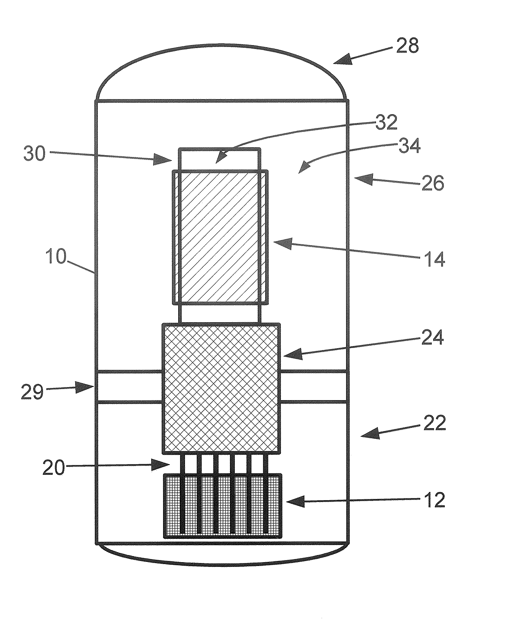
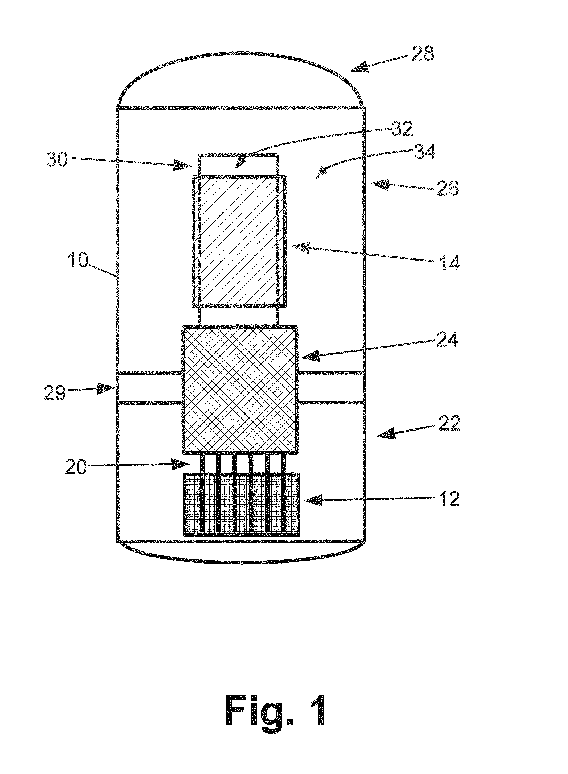
[0023]With reference to FIG. 1, an illustrative nuclear reactor vessel of the pressurized water reactor (PWR) type is diagrammatically depicted. An illustrated primary vessel 10 contains a reactor core 12, internal helical steam generators 14, and internal control rods 20. The illustrative reactor vessel includes four major components, namely: 1) a lower vessel 22, 2) upper internals 24, 3) an upper vessel 26

[0024]The lower vessel 22 of the illustrative reactor vessel 10 of FIG. 1 contains the reactor core 12, which can have substantially any suitable configuration. One suitable configuration includes a stainless steel core former structure that contains the fuel assemblies and is replaceable in order to refuel the reactor, and which is supported by the lower vessel. The illustrative upper vessel 26 houses the steam generators 14 for this illustrative PWR which has an internal steam generator design (sometimes referred to as an integral PWR design). In FIG. 1, the steam generator 14...


PUM


Abstract

A control rod drive mechanism (CRDM) comprises a lead screw, a motor threadedly coupled with the lead screw to linearly drive the lead screw in an insertion direction or an opposite withdrawal direction, a latch assembly secured with the lead screw and configured to (i) latch to a connecting rod and to (ii) unlatch from the connecting rod, the connecting rod being free to move in the insertion direction when unlatched, and a release mechanism configured to selectively unlatch the latch assembly from the connecting rod.

Description

BACKGROUND[0001]In a pressurized water reactor (PWR) or other type of nuclear reactor, movable control rods are used to control the nuclear reaction. The control rods include a neutron absorbing material, and are arranged to be inserted into the reactor core. In general, the further the control rods are inserted into the core, the more neutrons are absorbed and the more the nuclear reaction rate is slowed. Precise control of the amount of insertion, and accurate measurement of same, is useful in order to precisely control the reactivity. The control rods drive mechanism (CRDM) provides this control.[0002]In an emergency, the control rods can be fully inserted in order to quickly quench the nuclear reaction. In such a “scram”, it is useful to have an alternative fast mechanism for inserting the control rods. Additionally or alternatively, it is known to have dedicated control rods that are either fully inserted (thus turning the nuclear reaction “off”) or fully withdrawn (thus making...

Claims


Application Information

Patent Timeline
IPC IPC(8): G21C7/06
CPCY02E30/39G21C7/14Y02E30/30Y02E30/10G21C7/10
Inventor DESANTIS, PAUL K.
Owner BWXT NUCLEAR OPERATIONS GRP
Why Eureka
Try Eureka