Portable equipment detecting system
- Summary
- Abstract
- Description
- Claims
- Application Information
AI Technical Summary
Benefits of technology
Problems solved by technology
Method used
Image
Examples
first embodiment
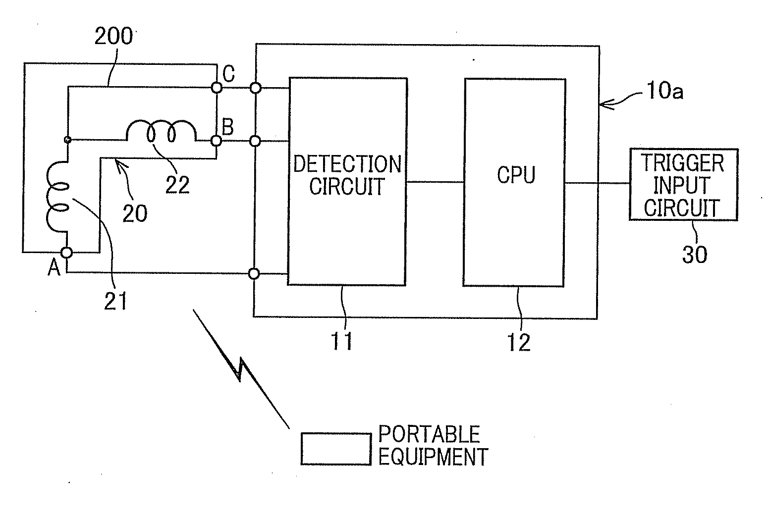
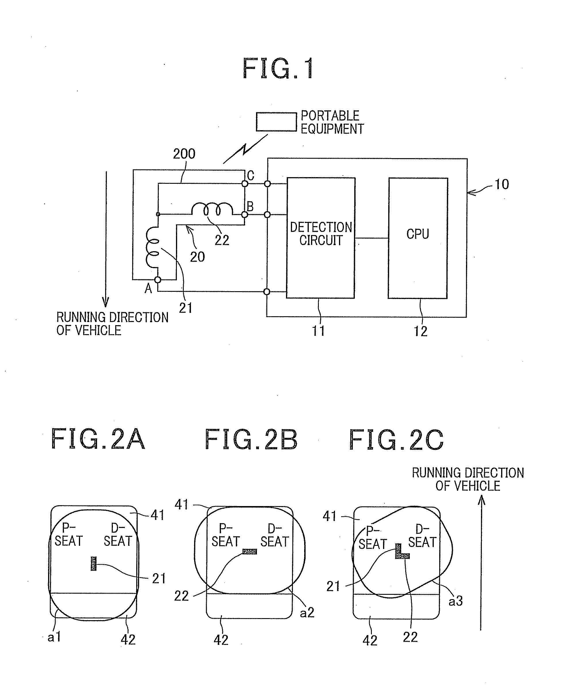
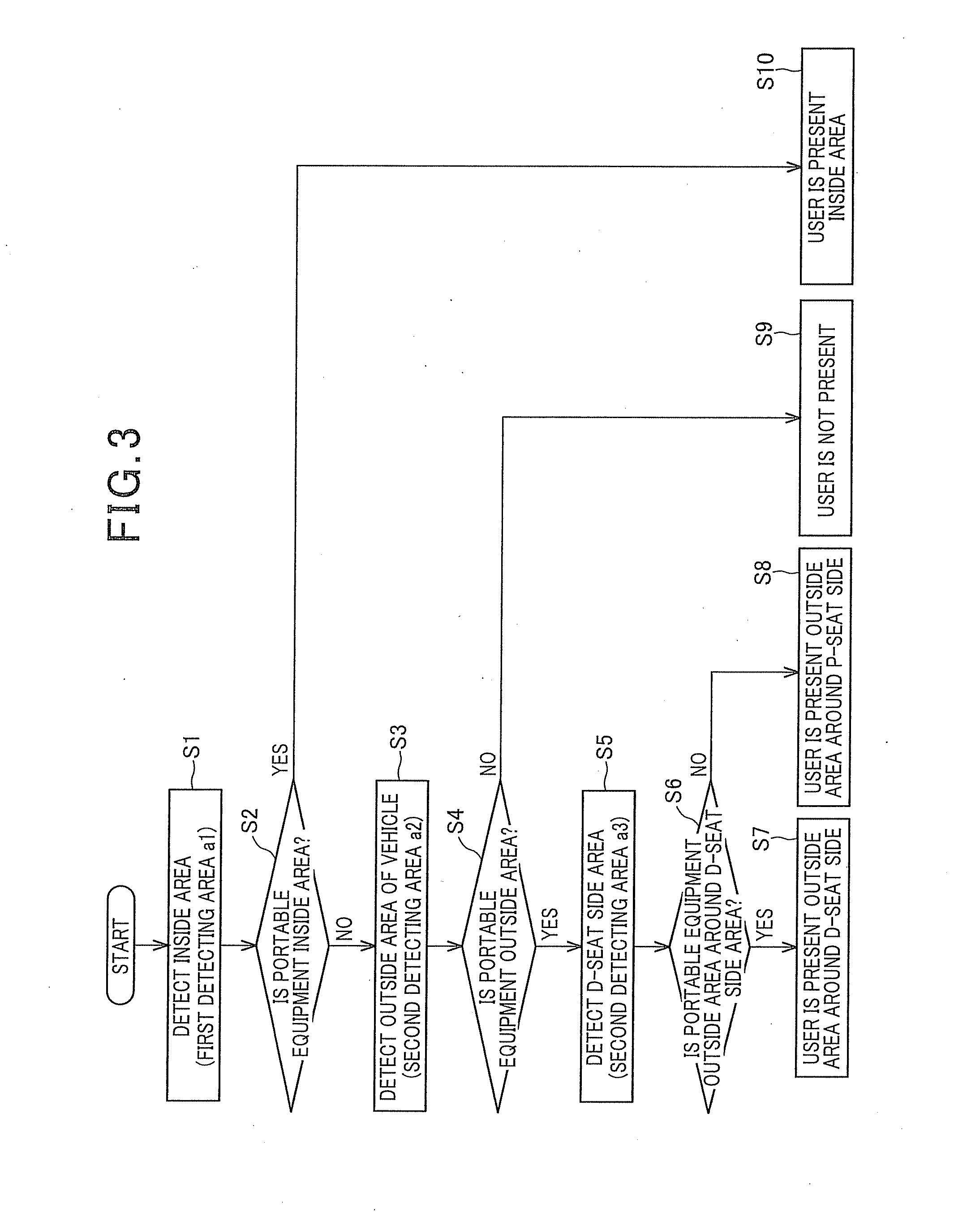
[0042]With reference to FIGS. 1 to 3, a portable equipment detecting system according to a first embodiment of the present invention is described as follows. FIG. 1 is a block diagram showing an overall configuration of the portable equipment detecting system according to the first embodiment.
[0043]The portable equipment detecting system according to the first embodiment is mounted on the vehicle and configured to mutually communicate with the portable equipment thereby detecting the location of the portable equipment. This portable equipment detecting system is applied to, for example, a smart entry system which is used to control doors of the vehicle to be locked / unlocked based on a verification result of an identification (ID) code exchanged between the detecting system and the portable equipment via a bidirectional communication (mutual communication), and a smart start system which is used to control lock / unlock of the steering and enable / disable starting the engine.
[0044]As sh...
second embodiment
[0066]Next, with reference to FIG. 6, the portable equipment detecting system according to the second embodiment of the present invention is described. The overall configuration portable equipment detecting system according to the second embodiment is the same as the one of the first embodiment. Hence, the explanation thereof is omitted (Please see FIG. 1). Regarding the operation procedure of the portable equipment detecting system according to the second embodiment, since most function blocks are identical to the function blocks of the first embodiment, the explanation for the identical blocks is omitted. In the flowchart as shown in FIG. 6, steps having the same contents of the flowchart as shown in FIG. 3 have the same step number. It is noted that the difference between the portable equipment detecting system according to the first embodiment and the portable equipment detecting system according to the second embodiment is whether or not the portable equipment is in the trunk s...
third embodiment
[0070]Next, with reference to FIGS. 7 to 9, hereinafter will be described a portable equipment detecting system according to a third embodiment. Since most function blocks configures the third embodiment are identical to the one of the above-described first embodiment, explanation thereof is omitted. For instance, in a block diagram as shown in FIG. 7, function blocks identical to those of the first embodiment are applied with the same reference numbers as the blocks in FIG. 1. The portable equipment detecting system according to the third embodiment differs from the one of the first embodiment in the power-supplied states, that is, a variable current-set circuit 13 and a variable voltage-set circuit 14 are added to the configuration used to make additional power-supplied states for the antenna 20 (i.e., first element 21 and second element 22), a fourth power-supplied state and a fifth power-supplied state.
[0071]As shown in FIG. 7, the portable equipment detecting system includes th...
PUM
 Abstract
Description
Claims
Application Information
 - R&D
- Intellectual Property
- Life Sciences
- Materials
- Tech Scout
- Unparalleled Data Quality
- Higher Quality Content
- 60% Fewer Hallucinations
Browse by: Latest US Patents, China's latest patents, Technical Efficacy Thesaurus, Application Domain, Technology Topic, Popular Technical Reports.
© 2025 PatSnap. All rights reserved.Legal|Privacy policy|Modern Slavery Act Transparency Statement|Sitemap|About US| Contact US: help@patsnap.com


