
Apparatus for direct communication in a wireless system and method thereof

a wireless communication and wireless technology, applied in the field of wireless communication systems, can solve the problems of increasing the battery consumption of the terminal, limiting the use of the optimal communication path, and inconvenient operation, and achieve the effect of efficient operation

Inactive Publication Date: 2011-09-15
LG ELECTRONICS INC
View PDF92 Cites 111 Cited by
  • Summary
  • Abstract
  • Description
  • Claims
  • Application Information

AI Technical Summary

Benefits of technology

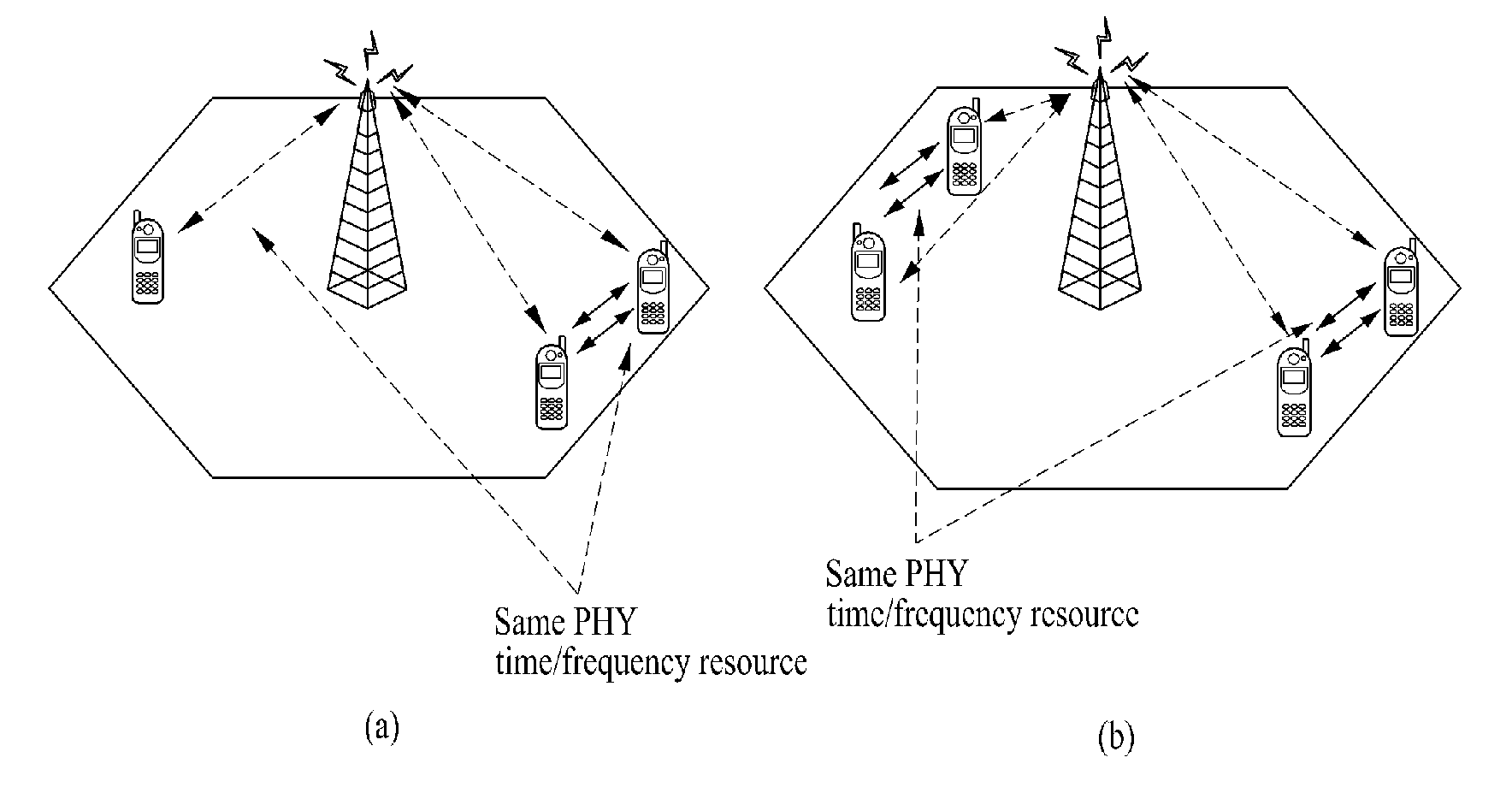
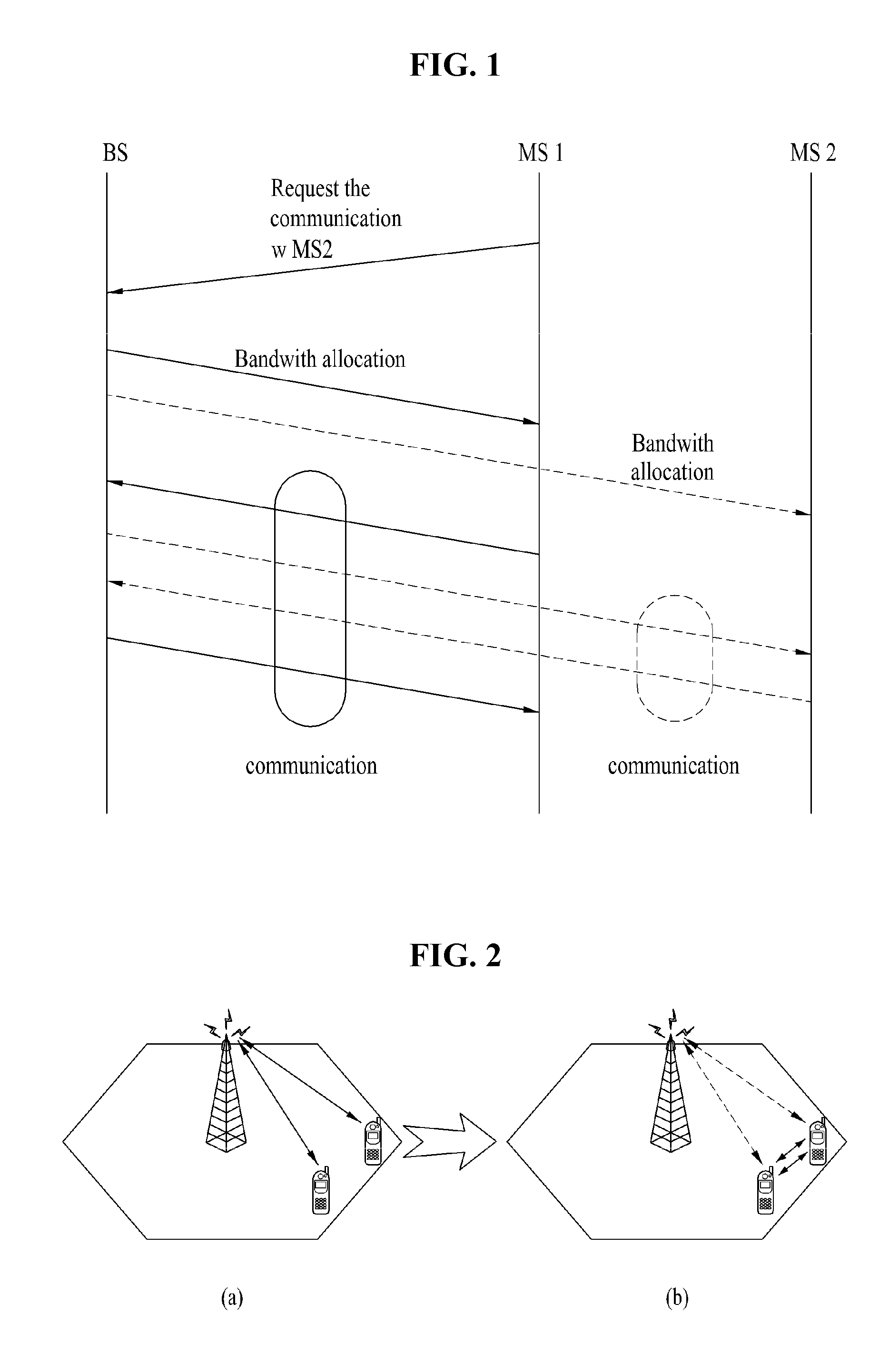
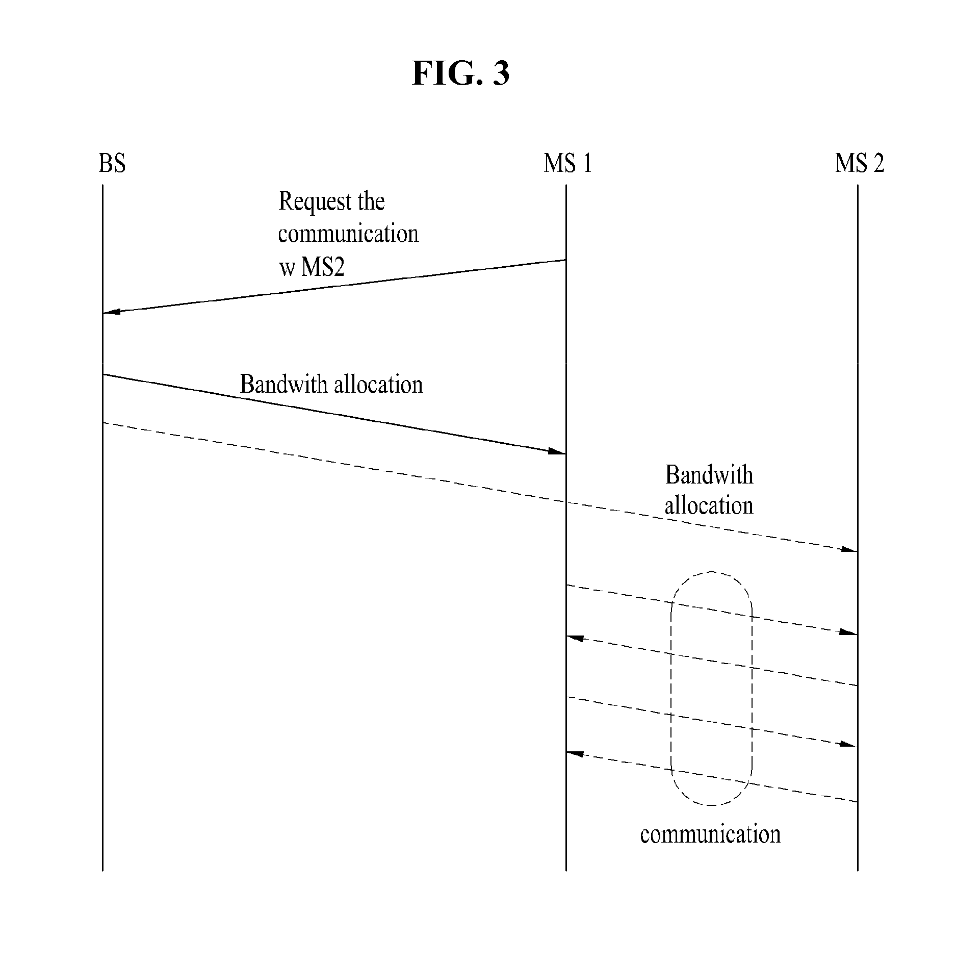
The present invention provides an apparatus and method for direct communication in a wireless communication system that overcomes limitations and disadvantages of existing technologies. The invention allows for efficient communication with low power by reusing allocated resources between terminals and measuring the quality of neighboring terminals to optimize the direct communication. The technical effects of the invention include efficient and low-powered direct communication between terminals and improved quality of communication through resource allocation optimization.

Problems solved by technology

Yet, this rule may be inefficient in accordance with an application or a channel configuration of terminal.
For instance, in case that a channel configuration of a terminal is vulnerable, limitation is put on using an optimal communication path by finding a new access path.
Therefore, although a specific terminal is located closer than a base station or a communication with a terminal in good channel status is necessary, it may happen that a signal is transmitted perform a communication via the base station using a high power, which raises battery consumption of a terminal.
Moreover, in aspect of the base station, an unnecessary transceiving of a simple forwarding type is performed.
However, as mentioned in the above description, a wireless communication system according to a related art consumes a considerable amount of energy for communications between terminals located in short range and also causes an unnecessary operation to a base station.

Method used


Image

  • Apparatus for direct communication in a wireless system and method thereof
  • Apparatus for direct communication in a wireless system and method thereof
  • Apparatus for direct communication in a wireless system and method thereof

Examples


Embodiment Construction

[0035]Reference will now be made in detail to the preferred embodiments of the present invention, examples of which are illustrated in the accompanying drawings. In the following detailed description of the invention includes details to help the full understanding of the present invention. Yet, it is apparent to those skilled in the art that the present invention can be implemented without these details. For instance, although the following descriptions are made in detail on the assumption that a mobile communication system includes IEEE (institute of electrical and electronics engineers) 802.16 system, the following descriptions are applicable to such a random mobile communication system as 3GPP (3rd generation partnership project) LTE (long term evolution) system and the like except unique features of the IEEE 802.16 system.

[0036]Occasionally, to prevent the present invention from getting vaguer, structures and / or devices known to the public are skipped or can be represented as bl...


PUM


Abstract

An apparatus for direct communication in a wireless communication system and method thereof are disclosed, by which a communication is efficiently enabled with a low power. In performing a direct communication in a first terminal of a wireless communication system, the present invention includes receiving a resource allocation information on a resource allocated to the direct communication from a base station and performing the direct communication with a second terminal using the allocated resource. In this case, the allocated resource is defined in either an uplink resource region of the base station or a downlink resource region of the base station and the allocated resource is divided into a transmission region for the direct communication and a receipt region for the direct communication.

Description

CROSS-REFERENCE TO RELATED APPLICATIONS[0001]Pursuant to 35 U.S.C. §119, this application claims the benefit of earlier filing date and right of priority to Korean Patent Application No. 10-2011-0011542, filed on Feb. 9, 2011, and U.S. Provisional Patent Application Nos. 61 / 314,167, filed on Mar. 16, 2010, and 61 / 313,806, filed on Mar. 15, 2010, the contents of which are incorporated by reference herein in their entirety.BACKGROUND OF THE INVENTION[0002]1. Field of the Invention[0003]The present invention relates to a wireless communication system, and more particularly, to an apparatus for direct communication in a wireless communication system and method thereof.[0004]2. Discussion of the Related Art[0005]Generally, a communication between terminals located in a near distance in-between can be defined as a peer-to-peer type. In the peer-to-peer communication, a random access scheme between communication subjects is defined and the communication subjects perform the communications ...

Claims


Application Information

Patent Timeline
Patent Type & Authority Applications(United States)
IPC IPC(8): H04W72/04
CPCH04W72/042H04W92/18H04W76/023H04W76/14Y02D30/70H04W72/23
Inventor LEE, HYUN WOOCHO, HAN GYUKWON, YEONG HYEON
Owner LG ELECTRONICS INC
Learn More