Method for handling material in a material conveying system, material conveying system and a separating device for a material conveying system

a conveying system and material technology, applied in the field of pneumatic material conveying systems, can solve the problems of inability to economically viable equip with their own partial-vacuum generating apparatus or with a separating device and a separate container, awkward use of vehicles in cramped spaces, heavy and noisy, etc., to achieve efficient storage, avoid drawbacks of prior-art solutions, and efficiently reduce space requirements

Inactive Publication Date: 2015-07-09
MARICAP OY
View PDF0 Cites 6 Cited by
  • Summary
  • Abstract
  • Description
  • Claims
  • Application Information

AI Technical Summary

Benefits of technology

[0014]The solution according to the invention has a number of important advantages. By means of the solutions of the invention the drawbacks of prior-art solutions can be avoided. By using a deep collection container as a separating device, the material conveyed into the collection container can be efficiently stored, and emptying of the container can be performed less frequently. Emptying of the collection container can be performed by lifting the collection container and by transferring the material that has collected in the container from an openable and closable aperture arranged in the bottom part of the container into the container of a transport means, such as of a garbage truck. The transport means can comprise a press for compressing the material so it becomes denser and a hoist for lifting the collection container. With the solution according to the invention, the separating device of a pneumatic pipe transport system for material and the collection container intended for temporary storage of the transported material can be efficiently combined. When the collection container is a so-called deep collection container, which is at least partly embedded to below the surface level of the ground, or corresponding surface level, the space requirement can be efficiently reduced. By arranging most of the volume of the collection container below the surface of the ground, and a relatively small part to be the visible part, a very environmentally suitable solution for a collection container is achieved. Owing to the large volume and the dimensions of the container, the collected material settles, i.e. compacts, in which case relatively more material fits into the collection container than into many small containers. When the collection container is arranged deep in the ground, the deep collection container remains colder in the summer, in which case any odor nuisance possibly caused by wastes is smaller. According to one preferred embodiment the deep collection container-separating device comprises a collection container and an external container, into which the collection container is arranged and from which the collection container is lifted for emptying. The solution according to the invention is suited for use in connection with many different types of pneumatic pipe transport systems for material. Systems using blowing for the conveying of material come into question also, in addition to partial-vacuum systems. When using partial-vacuum generating apparatus to achieve the pressure difference / transporting air flow needed in the conveying piping, a mobile partial-vacuum generating apparatus can be used effectively in connection with a material conveying system comprising the deep collection separating device of the invention to achieve the partial vacuum needed in the pneumatic transportation of material. In this case a dedicated fixed partial-vacuum generating apparatus is not needed in individual material conveying systems. The system thus enables the division of effective operating time of the partial-vacuum source between a number of material conveying systems. The system also enables the offering of the partial-vacuum source of the material conveying system as a service to properties. In addition, the invention enables an effective way to ensure material conveying by using a number of mobile partial-vacuum sources, in which case e.g. in a malfunction situation a primary partial-vacuum source can easily be replaced with a second mobile backup apparatus. The mobile partial-vacuum source according to the invention fits to function in more cramped locations also because it can be arranged in a vehicle in which space for wastes is not needed at the same time. The solution according to the invention effectively enables a different frequency for operation of the partial-vacuum source and for emptying of a container. According to an embodiment of the invention it is also conceivable that the partial-vacuum source arranged in the proximity of the deep collection separating device or separating devices is e.g. an immobile suction pump container or corresponding, with which the air flow / partial vacuum for conveying material from input points into the separating device is handled. This solution is particularly suitable in situations in which there are a number of deep collection separating devices in the same connection. The solution according to the invention offers the possibility to use an existing garbage truck or corresponding for emptying the collection container of the deep collection-separating device. The deep collection container / separating device according to the invention also gives the possibility for feeding in, via an openable and closable input aperture formed in the collection container, the type of material which is not, e.g. owing to its size or other properties, suited for conveying in a pneumatic pipe transport system for material. In the deep collection container-separating device according to the invention the flow of transporting air is acted upon in the chamber space of the separating device or in the output channel by bringing about a guiding effect for the transporting air in the opposite direction with respect to its direction of rotation. With this it is possible to significantly improve the material to be separated being prevented from displacing along with the transporting air towards the output channel. In this case e.g. waste particles, such as papers or plastic films or bags, do not get into the output aperture of the separating device and / or block the output aperture, and an operationally reliable deep collection container-separating device for a pneumatic wastes conveying system can be achieved. The desired effect can be achieved by arranging an output branch coupling in the wall of the output channel such that a flow of the transporting air from the output channel into the output branch coupling is achieved in a mainly tangential direction with respect to the wall of the output channel. This can be achieved e.g. by arranging the output branch coupling eccentrically in the output channel. The deep collection separating device according to the invention is suited to both material conveying systems, in which a formatter, i.e. a rotary shaper, is used to compact and / or shape the material to be conducted into the conveying piping from the input points, and to ordinary pneumatic pipe transport systems for material, in which systems material is fed in from an input point directly into the conveying piping.

Problems solved by technology

In this case in the initial phase of a construction project a situation is encountered wherein it is necessary to make sizable investments in equipment, even though the designed full capacity will not be needed in the system for years yet.
On the other hand, there are a lot of quite small sites, such as office properties, commercial properties, industrial properties and especially residential properties or other sites, in which it is desired to achieve a pneumatic pipe transport solution for wastes, but which are not economically viable to equip with their own partial-vacuum generating apparatus or with a separating device and a separate container.
The vehicles of these solutions typically both suck, compress and transport waste.
The vehicles are very large, heavy and noisy.
This makes the vehicles needed awkward to use in cramped spaces, such as in old city centers.
In addition, the vehicles needed become expensive in terms of costs.
On the other hand, a part of the wastes is often such that, owing to its size or other attribute, it cannot be satisfactorily transported in the piping.

Method used


Image

  • Method for handling material in a material conveying system, material conveying system and a separating device for a material conveying system
  • Method for handling material in a material conveying system, material conveying system and a separating device for a material conveying system
  • Method for handling material in a material conveying system, material conveying system and a separating device for a material conveying system

Examples


Embodiment Construction

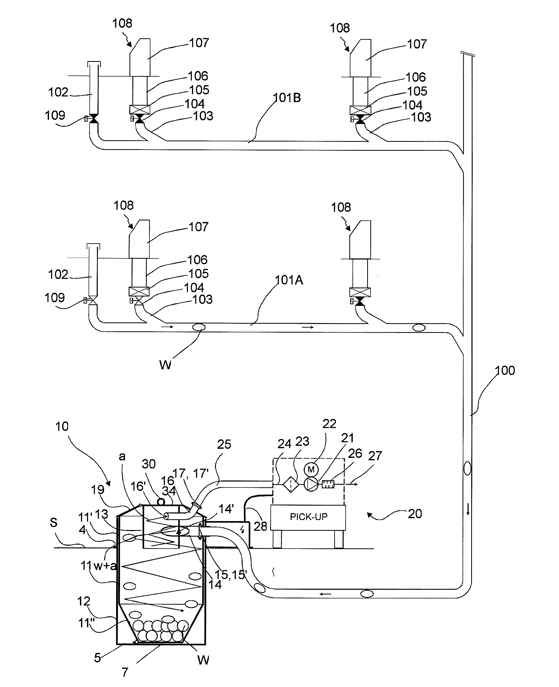
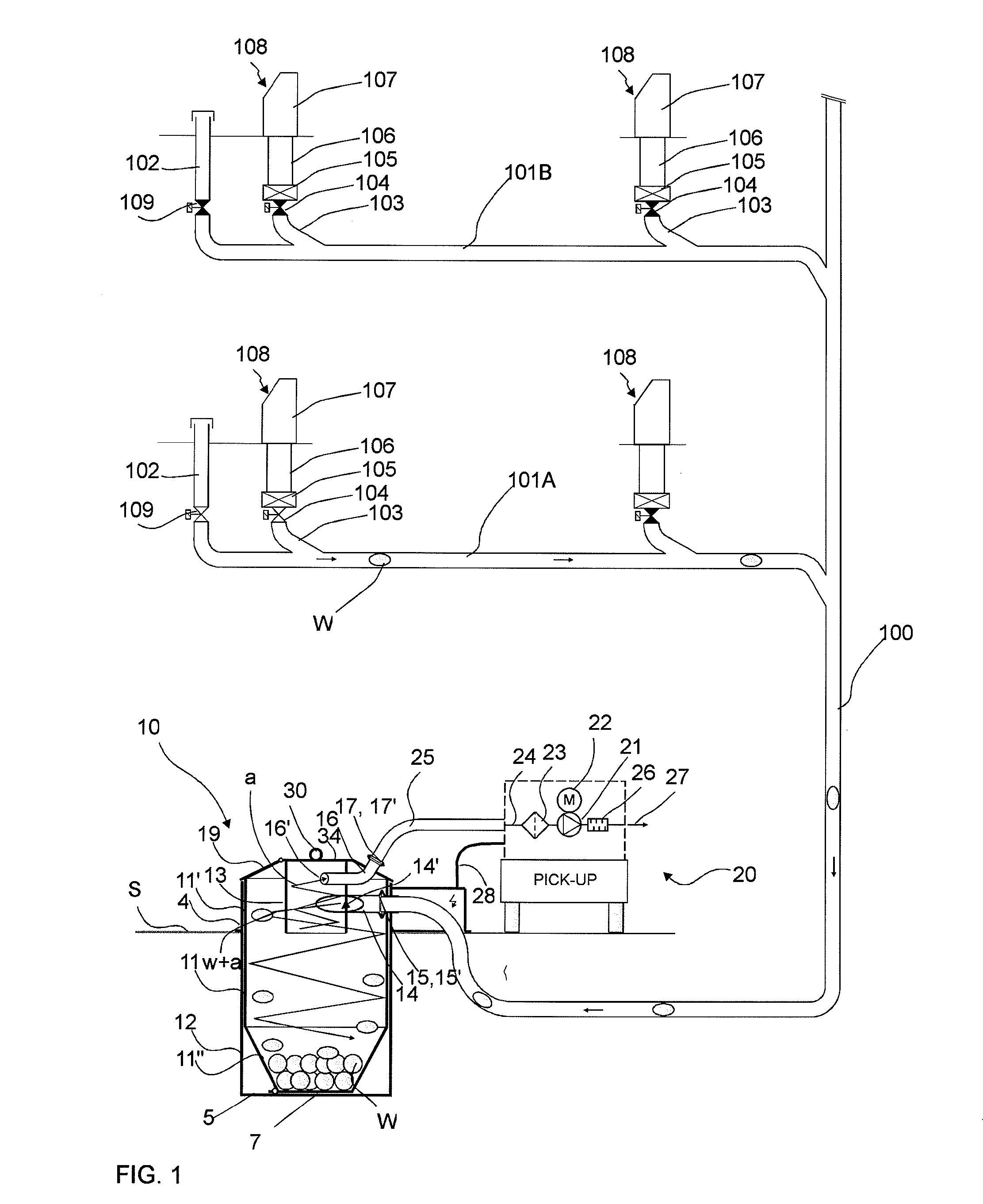
[0028]FIG. 1 presents a part of a pneumatic material conveying system, which part comprises a material conveying pipe 100, along the side of which at least one, typically many, input points 108 are arranged. The input point 108 is a feed-in station of material, more particularly of waste material, intended to be transported, from which station the material, more particularly waste material, such as household waste, or recyclable material intended to be transported is fed into the conveying system. The feed-in station 108 can also be a refuse chute, into which material is fed from input apertures on different floors of a building. The system can comprise a number of feed-in stations 108, from which the material intended to be transported is fed into conveying piping 100, 101A, 101B. By opening and closing a shut-off means, such as a valve means 104, that is possibly in connection with the feed-in station, material can be conveyed from an input point 108 into the conveying pipe 100. T...


PUM


Abstract

A method for handling material in a pneumatic material conveying system includes at least one input point of material, a material conveying pipe, connected to an input point, and a separating device or a container, in which the material to be transported is separated from the transporting air. A device is provided for achieving a pressure difference and/or a transporting air flow in the conveying pipe at least during the transportation of material. In the method the separating device is a deep collection container-separating device, into which material is conveyed from input points via a conveying pipe, and in that in the emptying phase the collection container is lifted with lifting means and the material that has collected in the collection container is emptied via an openable and closable aperture arranged in the bottom part of the collection container. A separating device and a material conveying system are provided.

Description

BACKGROUND OF THE INVENTION[0001]The object of the invention is a method as defined in the preamble of claim 1.[0002]The object of the invention is also a separating device according to claim 12 for a material conveying system.[0003]The object of the invention is also a material conveying system according to claim 20.[0004]The invention relates generally to pneumatic material conveying systems, such as to partial-vacuum transporting systems, more particularly to the collection and conveying of wastes, such as to the conveying of household wastes.[0005]Systems wherein wastes are conveyed in piping by means of suction and / or transporting air are known in the art. In these, wastes are moved long distances in the piping pneumatically, by means of suction and / or a pressure difference, together with the transporting air. The apparatuses are used for, among other things, the conveying of wastes in different institutions, for the conveying of household waste or for the conveying of other wa...

Claims


Application Information

Patent Timeline
Patent Type & Authority Applications(United States)
IPC IPC(8): B65F1/10B65G53/24B65F1/14B65G53/60B65F1/12B65F5/00B65G53/36
CPCB65F1/105B65F5/005B65G53/24B65F1/1447B65G53/60B65F1/125B65G53/36
Inventor SUNDHOLM, GORAN
Owner MARICAP OY
Why Eureka
Try Eureka