
High efficiency welding device

Inactive Publication Date: 2011-09-22
NI XUE FENG
View PDF2 Cites 0 Cited by
  • Summary
  • Abstract
  • Description
  • Claims
  • Application Information

AI Technical Summary

Benefits of technology

[0006]It is a principal object of the present invention to provide a welding device which drives the continuous welding electrode accurately and delivers the welding current to the welding operation with high efficiency.
[0007]It is an object of the present invention in providing two pairs of electrode driving means located in four positions in 360 degrees around the electrode to drive the electrode with high accuracy and efficiency.
[0008]It is an object of the present invention to provide a welding device which delivers the welding current to the continuous welding electrode efficiently with a minimum amount of resistance current loss.
[0009]It is another object of the present invention to provide a welding device which has a relatively light weight such that it can be handled with ease with one hand by the operator in the welding operation.
[0010]It is yet another object of the present invention to provide a welding device with relatively simple construction to minimize mechanical losses.

Problems solved by technology

Such construction is relatively complex in construction and the carriages are prone to jamming.
The length of welding electrode contributes to a higher current resistance in reducing the efficiency of the current provided to the welding operation.
Furthermore, longer carriages and driving system must be provided in the welding gun, which inherently increases the weight of the welding gun such that the gun must be held and operated awkwardly with two hands.

Method used


Image

  • High efficiency welding device
  • High efficiency welding device
  • High efficiency welding device

Examples


Embodiment Construction

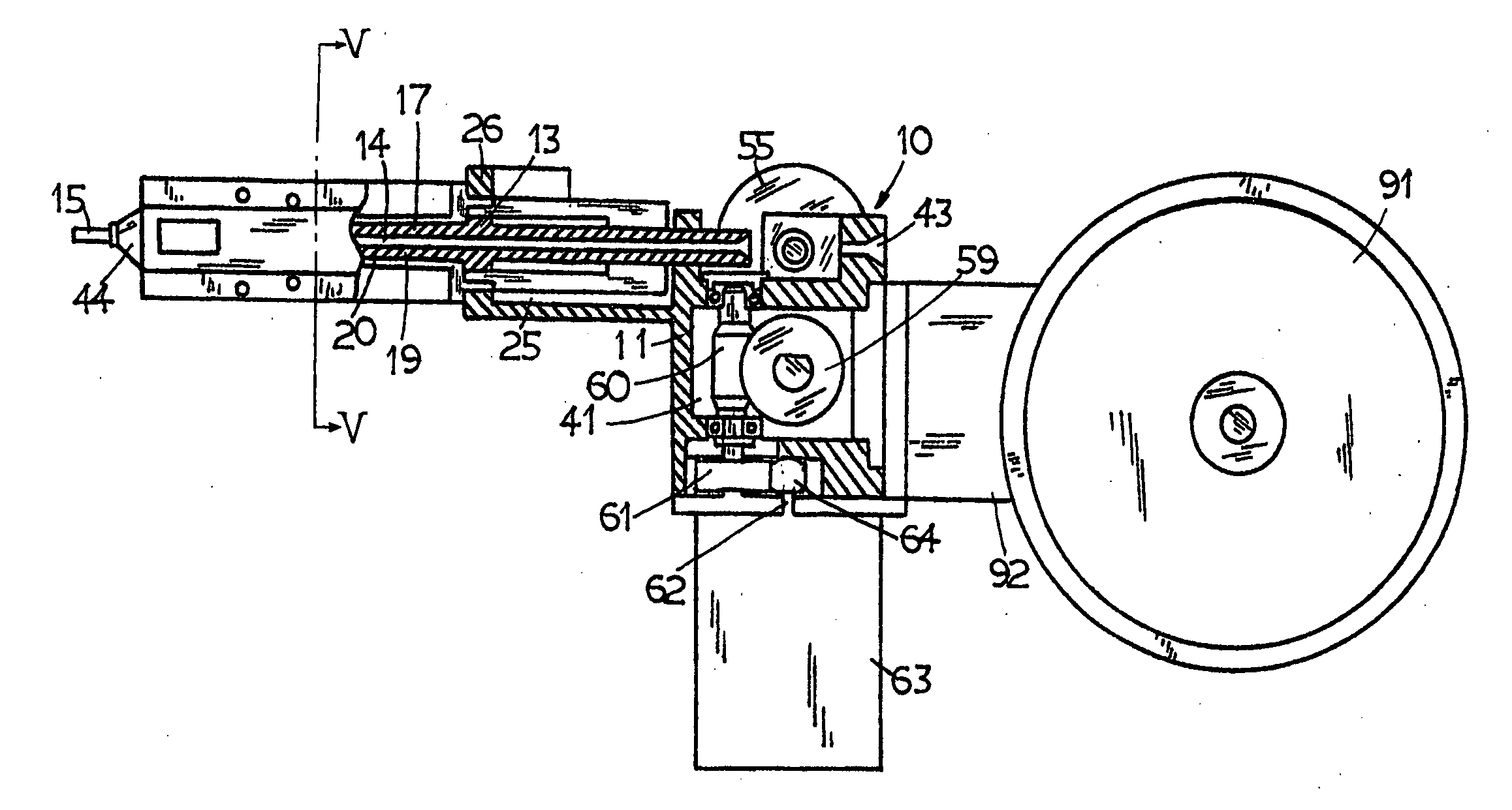
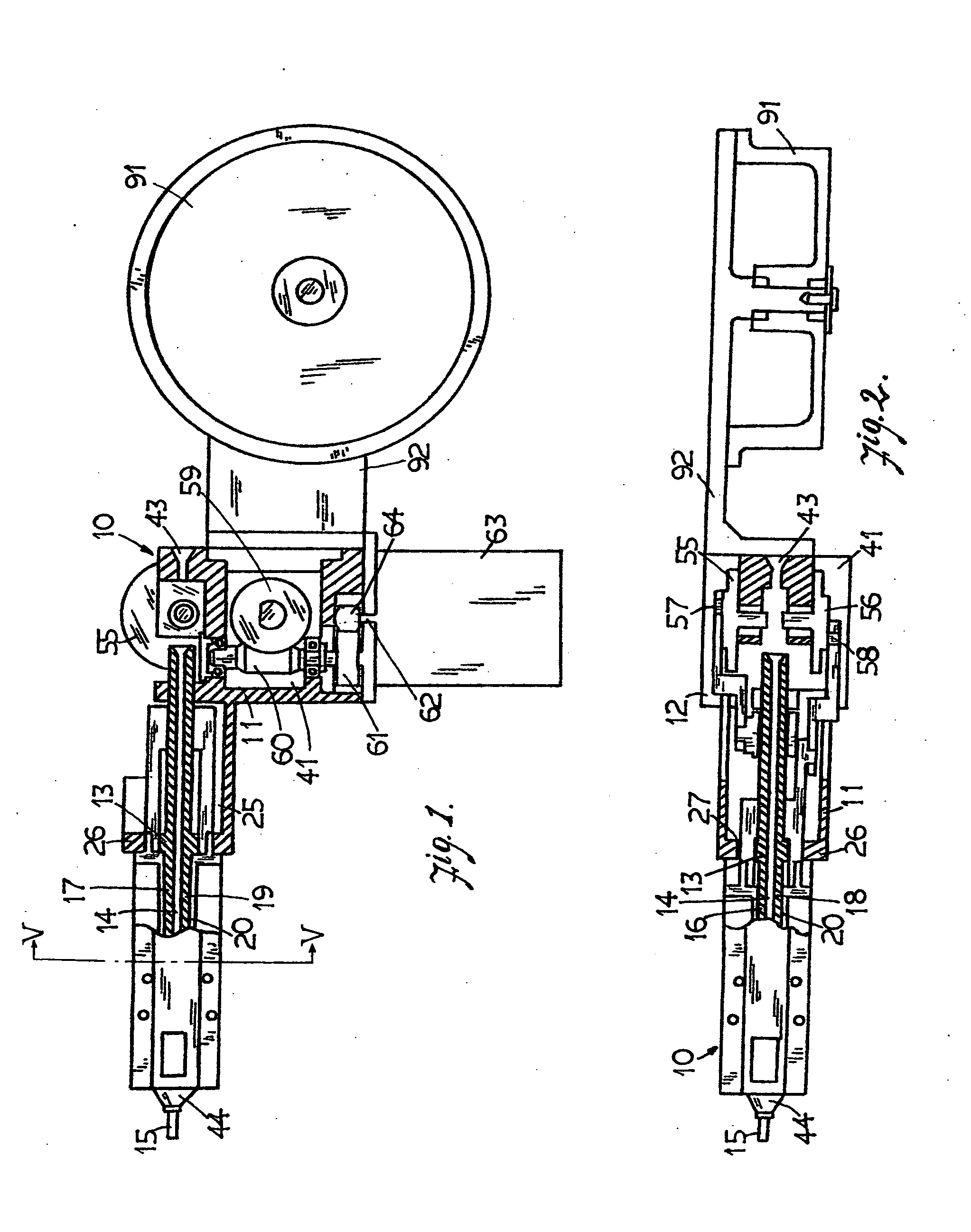
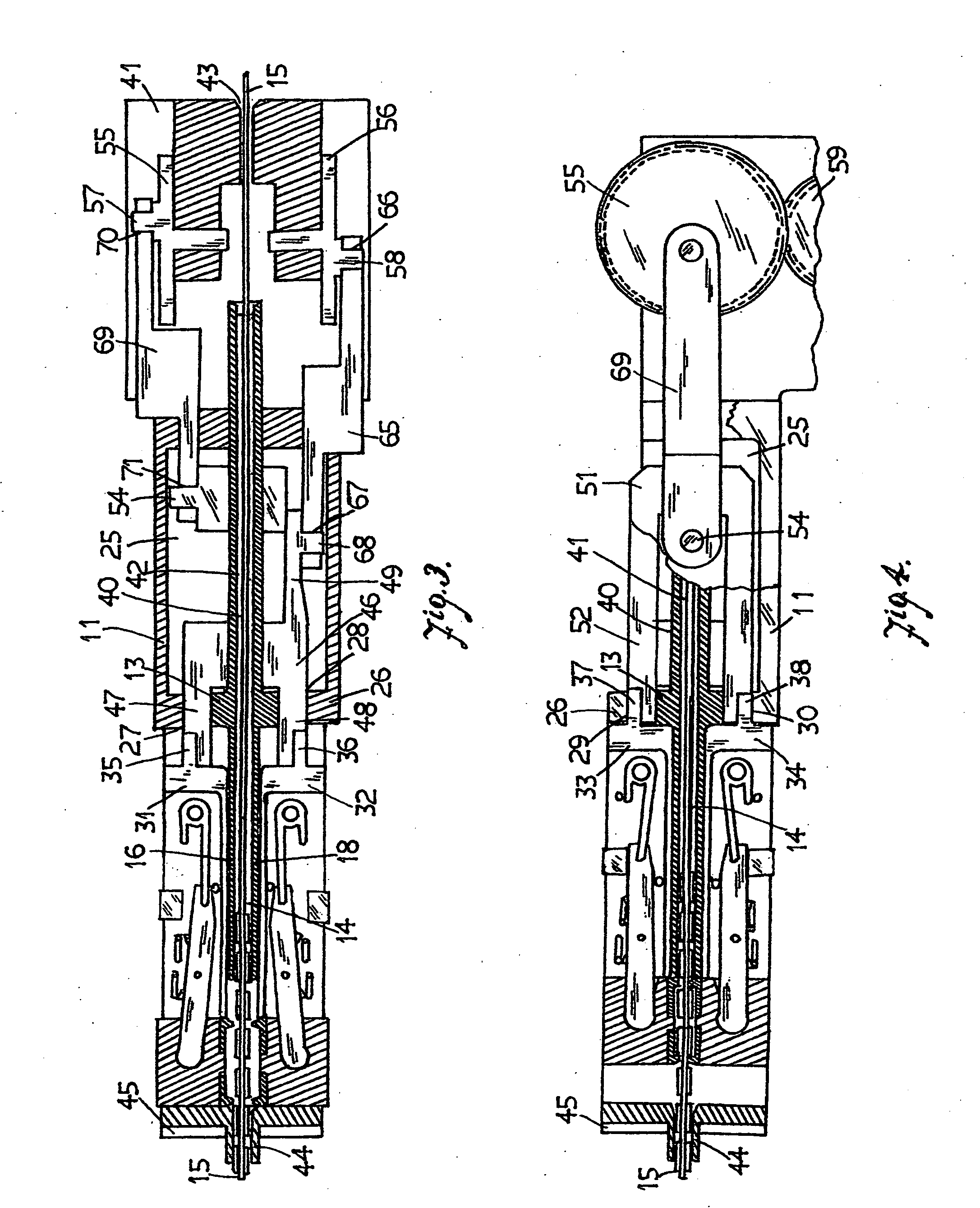
[0019]With reference to the drawings in which like reference numerals designate corresponding parts in the different views, the welding device 10 of the present invention has a main body 11 mounted within an outer enclosure 12. An elongated support block 13 as shown in the exemplary embodiment having a cylindrical cross shape cross section as best shown in FIG. 5 is located at the front portion of the main body 11. It can be understood by those skilled in the art that the support block may have a square cross sectional shape for providing the same function. A central opening 14 extending throughout the longitudinal axis of the support block 13 for guiding the continuous welding electrode 15 to pass through the device 10. The support block 13 has four elongated rectangular tracks 16, 17, 18, and 19 located at 0, 90, 180 and 270 positions with respect to one another around the circumferential surface of its front portion 20. Thus, the rectangular tracks 16, 17, 18 and 19 lie in two pl...


PUM

PropertyMeasurementUnit
Angleaaaaaaaaaa
Angleaaaaaaaaaa
Angleaaaaaaaaaa

Abstract

The high efficiency welding device has two pairs of clamps mounted in two pairs of sliders movable in a reciprocating movement relative to one another. One pair of sliders is mounted at 0 and 180 degree positions around the circumferential surface of a support block and the other pair of sliders is mounted at 90 and 270 degree positions. Each pair of clamps is in the close condition while moving forward in the reciprocating movement to clamp onto selected air gaps of the welding electrode to advance the electrode towards the work piece as well as delivering the welding current to the welding operation, and it is in the open condition releasing the grasp of the welding electrode while moving backward.

Description

BACKGROUND OF THE INVENTION[0001]1. Field of the Invention[0002]This invention relates to a high efficiency welding device for use with a continuous welding electrode. The device delivers the electrode towards the work piece to be welded with high welding current efficiency and precision.[0003]2. Background of the Invention[0004]A continuous welding electrode consists of a continuous metal core coated with a welding flux, and air gaps are formed on the flux coating in evenly spaced intervals. The metal core is exposed through the air gaps such that the electrode may be advanced with a welding device, commonly called a welding gun which has continuously moving carriers engaging with the air gaps for moving the electrode towards the working piece as well as for delivering the welding current to the metal core through the exposed air gaps. A welding operation may be continuously carried out with the welding current efficiently provided so as to produce a high quality continuous, strong...

Claims


Application Information

Patent Timeline
IPC IPC(8): B23K9/28
CPCB23K9/1336
Inventor NI, XUE FENG
Owner NI XUE FENG
Learn More