Patch antenna in wireless communication system and method for manufacturing the same

a wireless communication system and patch antenna technology, applied in the field of wireless communication system, can solve the problems of coupling loss, difficult to use patch antennas in high-frequency bands, and difficulty in increasing bandwidth

Inactive Publication Date: 2011-09-22
ELECTRONICS & TELECOMM RES INST +1
View PDF2 Cites 9 Cited by
  • Summary
  • Abstract
  • Description
  • Claims
  • Application Information

AI Technical Summary

Benefits of technology

[0011]In accordance with an embodiment of the present invention, a patch antenna in a wireless communication system includes: a patch antenna unit positioned at a predetermined point on a substrate; a first cover of a high-gain metamaterial of a different structure positioned over the patch antenna unit at a first distance from the substrate on which the patch antenna unit is positioned; and a second cover of a metamaterial of an identical structure positioned over the first cover at a second distance from the first cover, wherein the first cover has a quadrilateral grid formed only on an outer periphery of a dielectric surface of the first cover.
[0012]In accordance with...

Problems solved by technology

However, the patch antennas have a problem in that it is difficult to increase their bandwidth, and they induce substantial coupling loss, making it difficult to use the patch antennas in high-frequency bands.
However,...

Method used


Image

  • Patch antenna in wireless communication system and method for manufacturing the same
  • Patch antenna in wireless communication system and method for manufacturing the same
  • Patch antenna in wireless communication system and method for manufacturing the same

Examples


Embodiment Construction

[0023]Exemplary embodiments of the present invention will be described below in more detail with reference to the accompanying drawings. The present invention may, however, be embodied in different forms and should not be constructed as limited to the embodiments set forth herein. Rather, these embodiments are provided so that this disclosure will be thorough and complete, and will fully convey the scope of the present invention to those skilled in the art. Throughout the disclosure, like reference numerals refer to like parts throughout the various figures and embodiments of the present invention.

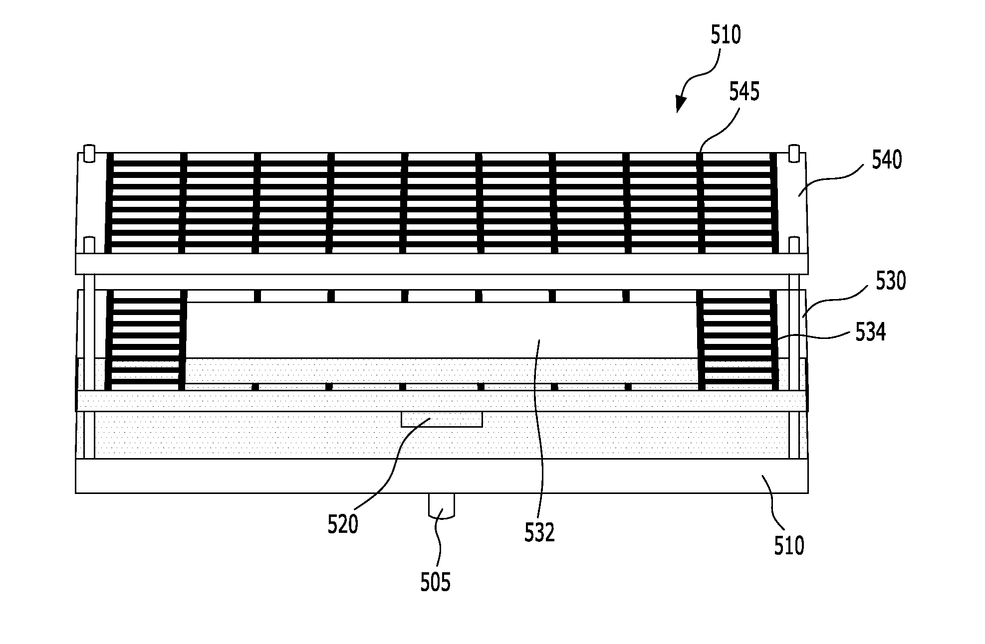
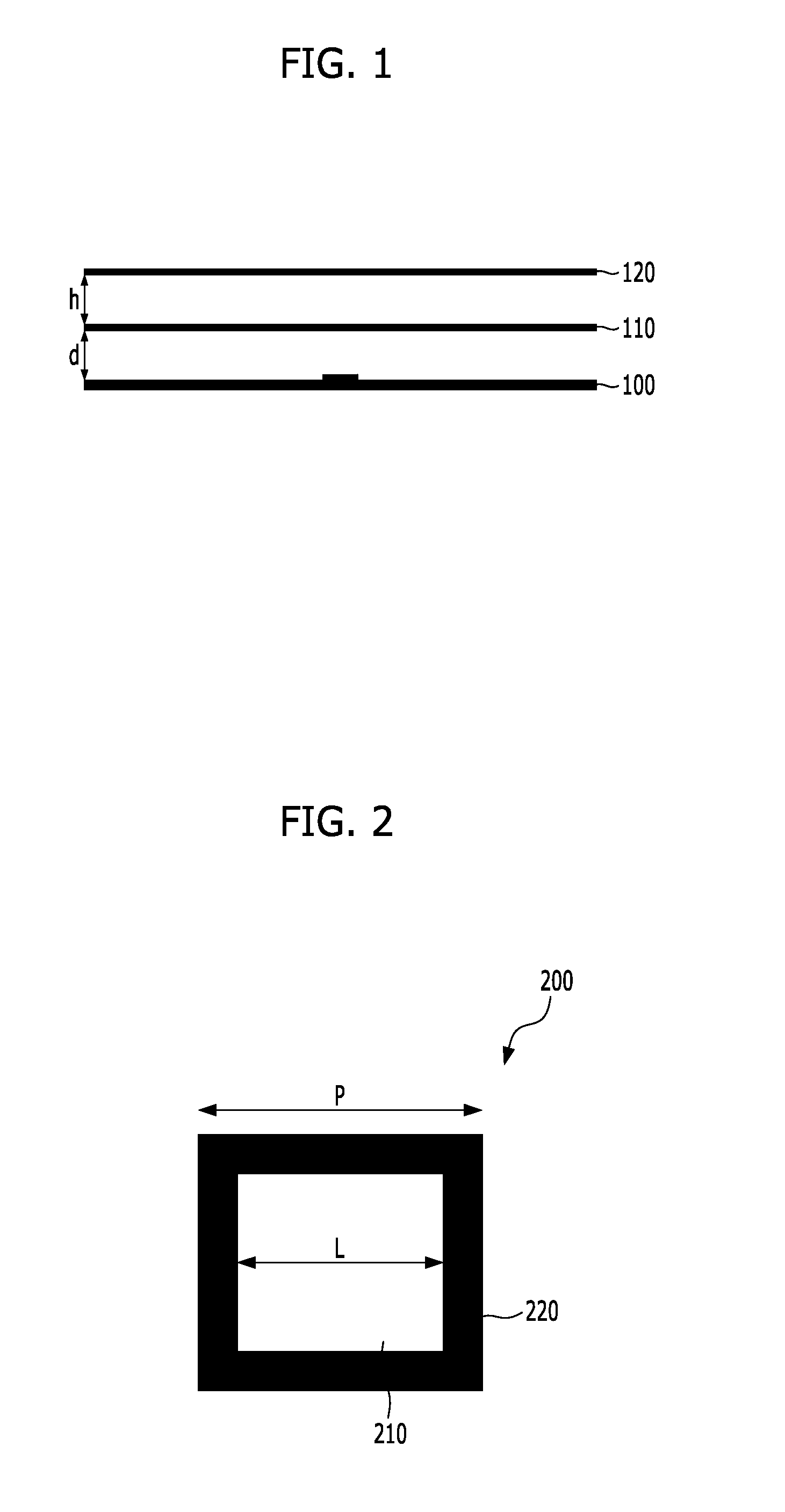
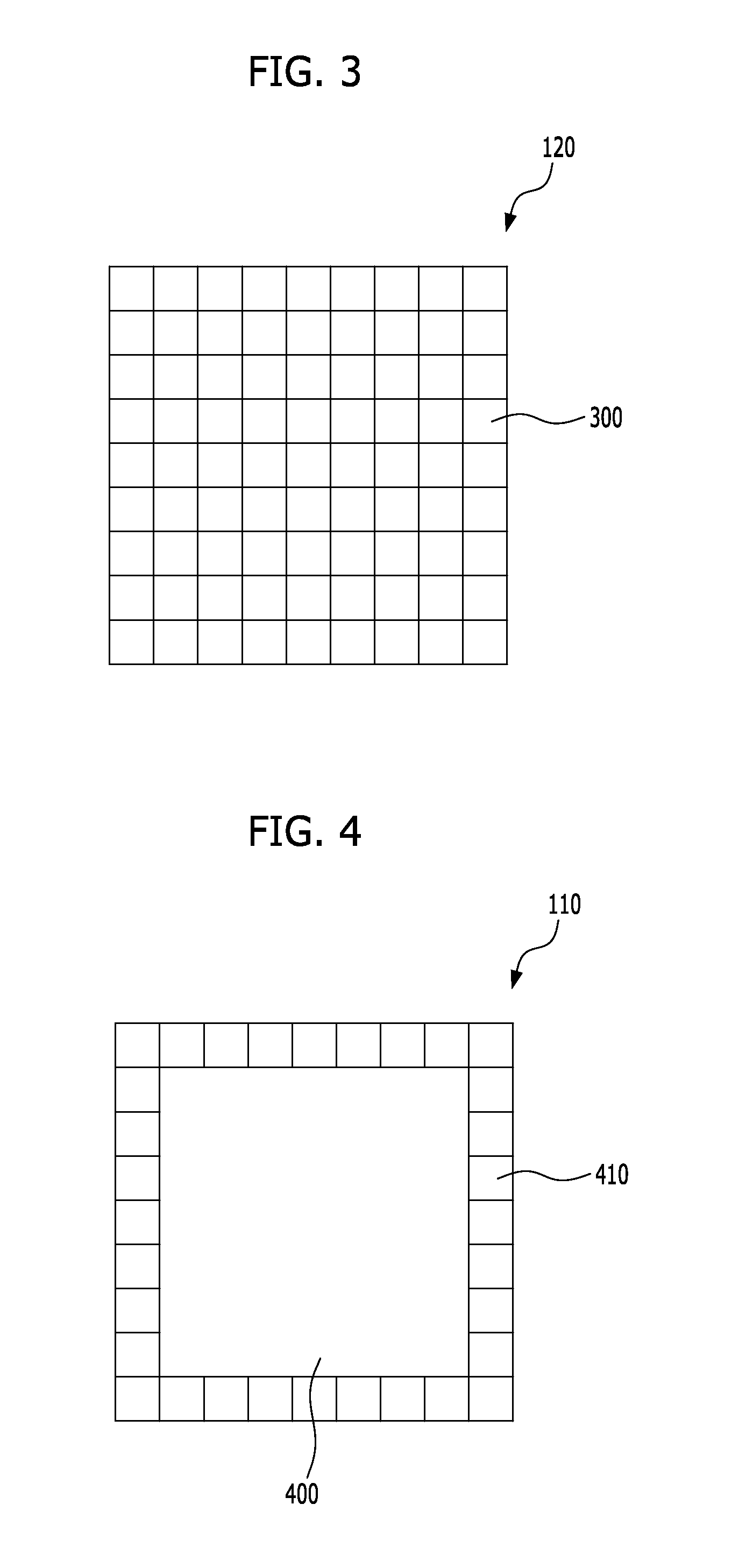
[0024]The present invention proposes a patch antenna using a cover of a high-gain metamaterial structure and thus having high gain in a wireless communication system, and a method for manufacturing the patch antenna. In accordance with an embodiment of the present invention, a patch antenna unit is formed on a substrate, and first and second covers are successively positioned over the patc...


PUM


Abstract

A patch antenna in a wireless communication system includes a patch antenna unit positioned at a predetermined point on a substrate; a first cover of a high-gain metamaterial of a different structure positioned over the patch antenna unit at a first distance from the substrate on which the patch antenna unit is positioned; and a second cover of a metamaterial of an identical structure positioned over the first cover at a second distance from the first cover. The first cover has a quadrilateral grid formed only on an outer periphery of a dielectric surface of the first cover.

Description

CROSS-REFERENCE TO RELATED APPLICATIONS[0001]The present application claims priority of Korean Patent Application No. 10-2010-0025449, filed on Mar. 22, 2010, which is incorporated herein by reference in its entirety.BACKGROUND OF THE INVENTION[0002]1. Field of the Invention[0003]Exemplary embodiments of the present invention relate to a wireless communication system; and, more particularly, to a patch antenna using a cover of a high-gain metamaterial structure and thus having high gain in a wireless communication system, and a method for manufacturing the patch antenna.[0004]2. Description of Related Art[0005]Various types of antennas have been proposed to transmit / receive signals in wireless communication systems, and patch antennas, among them, have the advantages of compact sizes, lightness, ease of fabrication, and low costs. However, the patch antennas have a problem in that it is difficult to increase their bandwidth, and they induce substantial coupling loss, making it diffi...

Claims


Application Information

Patent Timeline
IPC IPC(8): H01Q15/10
CPCH01Q15/0086H01Q9/0407
Inventor LEE, NAM-KIYANG, SEUNG-IN
Owner ELECTRONICS & TELECOMM RES INST
Why Eureka
Try Eureka