Portable transmitter with push switch and touch sensor

a technology of touch sensor and portable transmitter, which is applied in the direction of mechanical pattern conversion, instruments, cathode-ray tube indicators, etc., can solve the problems of reducing the operating life of the portable transmitter battery b>100, and sacrificing safety. , to achieve the effect of reducing the physical burden on the user's operation, minimizing the consumption of electric energy in the power source, and sacrificing safety

Inactive Publication Date: 2011-09-22
DENSO CORP
View PDF5 Cites 26 Cited by
  • Summary
  • Abstract
  • Description
  • Claims
  • Application Information

AI Technical Summary

Benefits of technology

[0015]It is therefore an object of the invention to provide a portable device designed to decrease a physical burden on a user's operation on a push switch without sacrificing the safety and to minimize the consumption of electric energy in a power source.
[0017]Specifically, when the push switch is depressed, and the touch sensor is touched by, for example, a user of the controlled device, the portable device outputs a radio signal indicative of the given instruction to the controlled device and continues to output such a radio signal for a period of time in which the touch sensor is kept touched even after the user releases the push switch. In other words, once the operating instruction has been outputted to the controlled device, the user is required only to touch the touch sensor in order to make the controlled device continue the operation. This eliminates the need for the user to continue the operation on the push switch until completion of the operation of the controlled device, thus resulting in a decrease in physical burden on the user.
[0018]In case of emergency where the controlled device should be stopped, the user is required only to stop touching the touch sensor to disable the controlled device, thereby ensuring the safety of the operation of the controlled device quickly.
[0019]The electric power continues to be supplied to the touch sensor for the given period of time in response to the depression of the push switch. Such a period of time may be set to only the length of time required by the radio transmitter to continue to transmit the operating instruction to the controlled device, thus minimizing the consumption of electric energy in the power source.

Problems solved by technology

This, however, may result in the following risk.
If the user drops and loses the portable transmitter 100 after the lift-up seat 200 has started to move in response to the operating instruction from the portable transmitter 100, it will result in impossibility of stopping the lift-up seat 200 urgently.
The tough switches, however, need be supplied with electric power to operate at all the time, thus resulting in a decrease in operating life of a battery of the portable transmitter 100.
The above problem is thought of as also being encountered in automotive power sliding door systems or power backdoor systems designed to operate for a period of time in which operating instructions, as outputted from the portable transmitter through a radio wave, are received.
This eliminates the need for the user to continue the operation on the push switch until completion of the operation of the controlled device, thus resulting in a decrease in physical burden on the user.

Method used


Image

  • Portable transmitter with push switch and touch sensor
  • Portable transmitter with push switch and touch sensor
  • Portable transmitter with push switch and touch sensor

Examples


Embodiment Construction

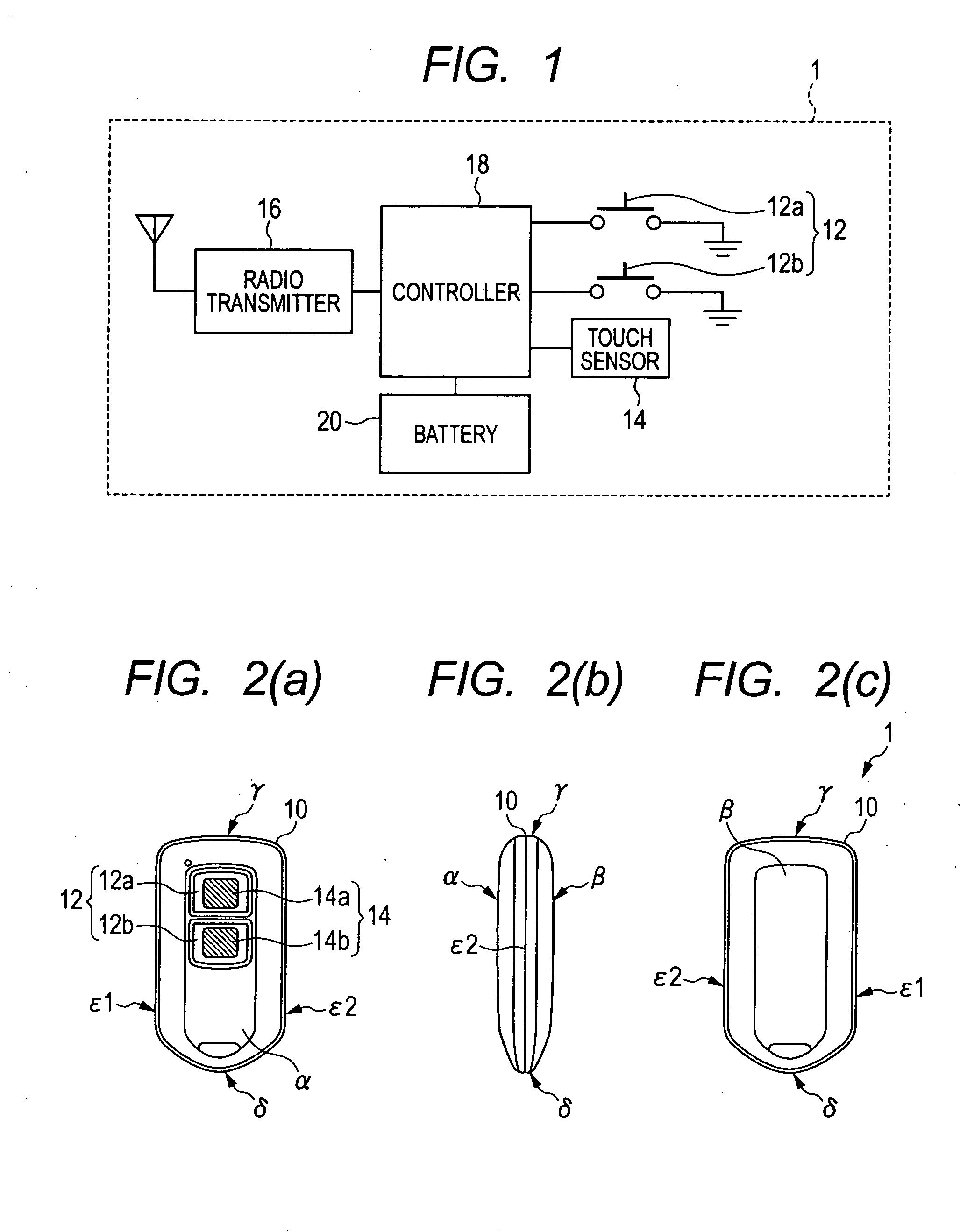
[0041]Referring to the drawings, wherein like reference numbers refer to like parts in several views, particularly to FIG. 1, there is shown a portable transmitter 1 according to the embodiment.

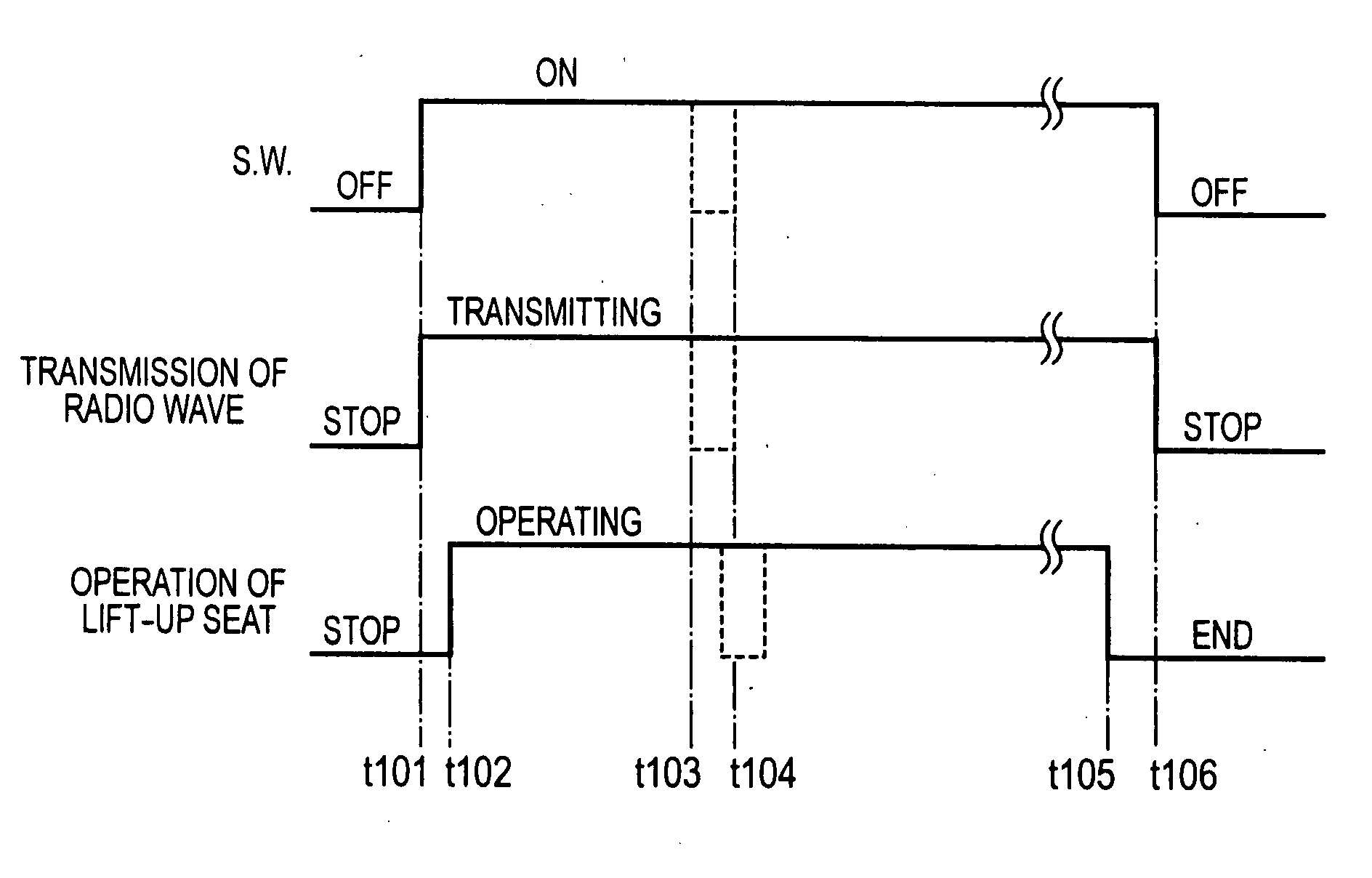
[0042]The portable transmitter 1 is designed as a remote wireless transmitter to output operating instructions in the form of radio waves to the lift-up seat 200, as discussed in the introductory part of this application with reference to FIG. 7(a). The portable transmitter 1 works to selectively output radio signals carrying a rotating-and-lowering instruction (which will also be referred to as an extending instruction below) to rotate the lift-up seat 200 from inside to outside an automotive vehicle and lower it to ground and a retracting instruction to retract the lift-up seat 200 into the vehicle.

[0043]The portable transmitter 1 is equipped with a retracting switch 12a, a rotating-and-lowering switch 12b, touch sensors 14, a radio transmitting unit 16, a controller 18, and a battery 20 wh...


PUM


Abstract

A portable transmitter is provided which transmits an operating instruction in the form of a radio wave to a controlled device which continues to operate while receiving the operating instruction. The portable transmitter includes a push switch and a touch sensor. The portable transmitter works to supply the electric power to the touch sensor for a given period of time in response to depression of the push switch. When the touch sensor senses a user's touch thereon, and the push switch is depressed, the portable transmitter transmits the operating instruction to the controlled device and continues such transmission as long as the touch sensor senses the touch thereon regardless of the depression of the push switch. In other words, once the operating instruction has been outputted to the controlled device, the user is required only to touch the touch sensor in order to make the controlled device continue the operation.

Description

CROSS REFERENCE TO RELATED DOCUMENT[0001]The present application claims the benefits of Japanese Patent Application No. 2010-64907 filed on Mar. 19, 2010, the disclosure of which is incorporated herein by reference.BACKGROUND[0002]1. Technical Field[0003]The present invention relates generally to a portable transmitter which transmits operating instructions in the form of a radio wave to a controlled device installed, for example, in an automotive vehicle.[0004]2. Background Art[0005]Japanese Patent First Publication No. 6-252782 discloses a portable transmitter which transmits start instructions in the form of a radio wave to an engine installed in a two-wheel vehicle such as a motorcycle. The portable transmitter has two pushbutton switches installed in opposed ends of a casing thereof. The pushbutton switches are electrically connected in series with each other. Only when the pushbutton switches are both placed in an on-state simultaneously, the portable transmitter outputs the s...

Claims


Application Information

Patent Timeline
Patent Type & Authority Applications(United States)
IPC IPC(8): G06F3/041
CPCB60N2/245
Inventor KOYA, HIDETAKA
Owner DENSO CORP
Why Eureka
Try Eureka