

Relay failure detecting device, power-supply device, image forming apparatus, relay failure detecting method, and computer program product
a technology of relay failure and detection device, which is applied in the direction of relays, contact testing/inspection, electrical apparatus, etc., can solve the problems of photo couplers' electrical power consumption
- Summary
- Abstract
- Description
- Claims
- Application Information
AI Technical Summary
Benefits of technology
Problems solved by technology
Method used
Image

Examples
first embodiment
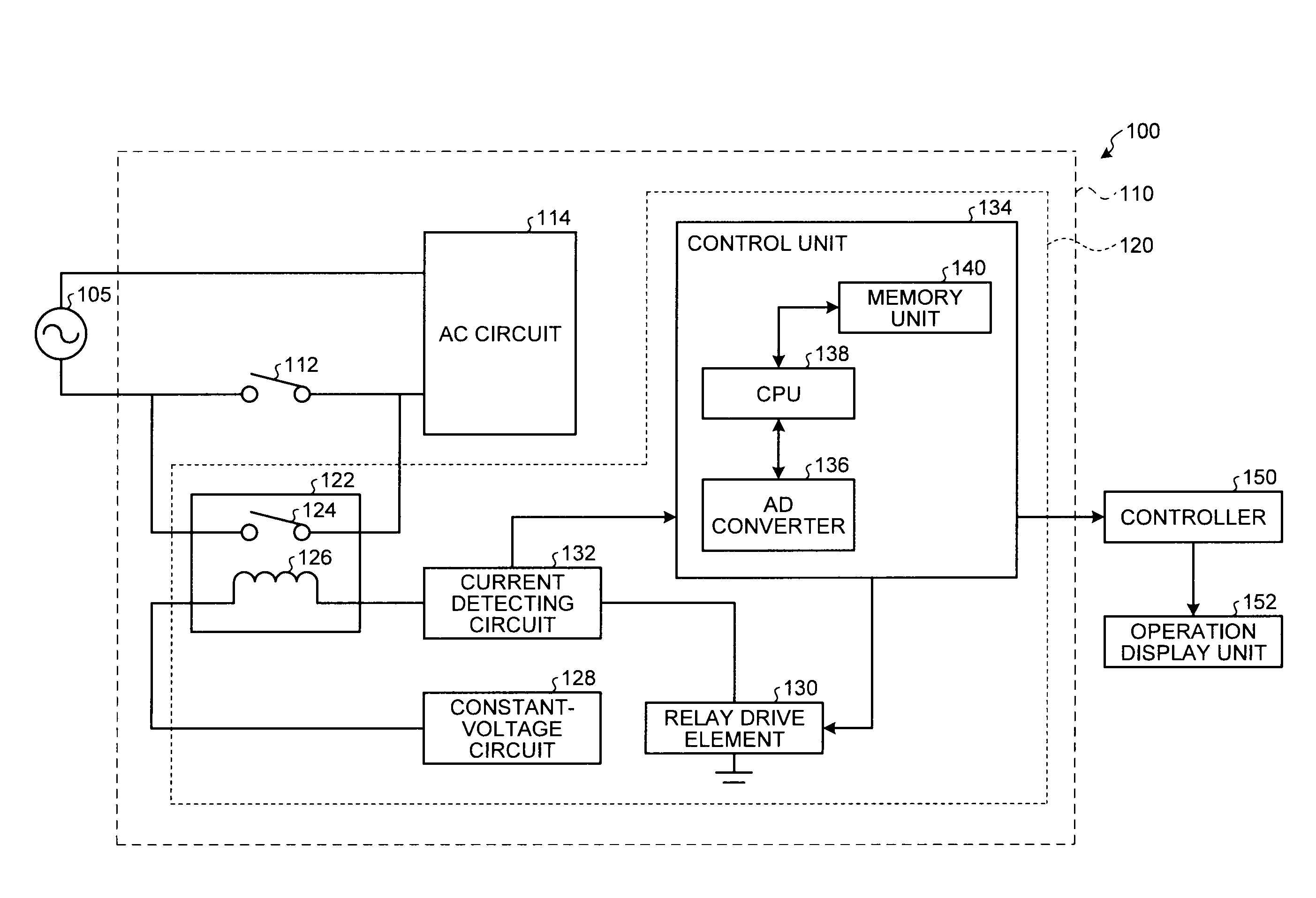
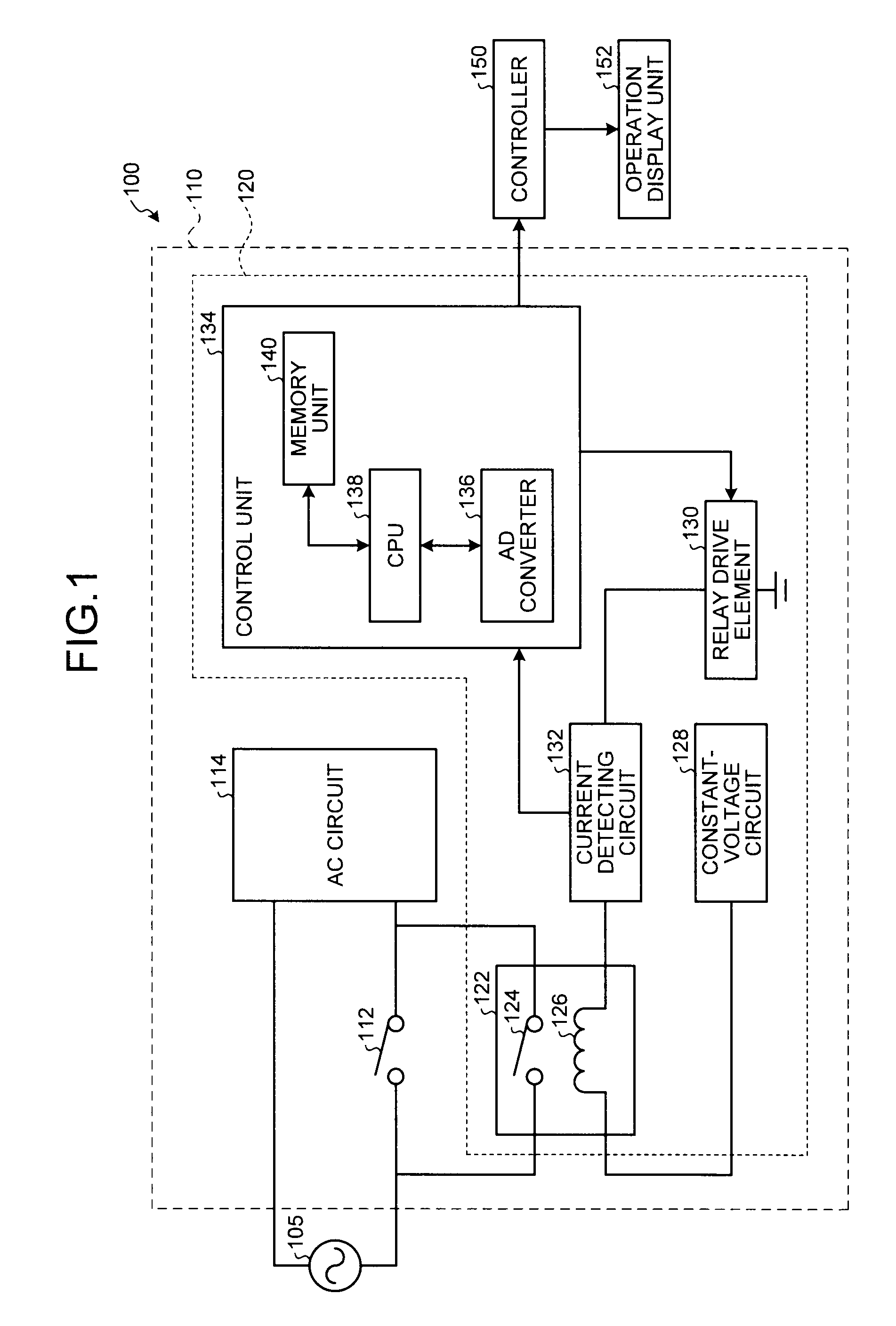
[0036]In a first embodiment according to the present invention, the explanation is given for a case of detecting a failure in a shutdown relay. Herein, a “shutdown relay” points to a relay that is mounted in parallel with an AC switch for the purpose of enhancing the security and protecting a hard disk drive (HDD). Even if the AC switch is abruptly turned OFF during the process of writing data in the HDD, the shutdown relay supplies power through a pathway on the side thereof and, only after the process of writing is complete, stops supplying power. Hence, the HDD is protected. Meanwhile, herein, a relay for which an occurrence of a failure needs to be detected is not limited to a shutdown relay.
[0037]During normal functioning of a relay, opening and closing of the relay contact causes a change in the inductance of an internal coil of the relay. However, when a failure occurs, the relay contact does not open or close. Hence, no change occurs in the inductance of the internal coil of...
second embodiment
[0064]In a second embodiment according to the present invention, the explanation is given for a case when a failure in a relay is detected by comparing the differential values calculated from the current values with the differential values obtained during the previous calculation. The following explanation is given with the focus on the dissimilarity between the first embodiment and the second embodiment. Meanwhile, the constituent elements having the same function as described in the first embodiment are referred to by the same naming / symbols, and the explanation thereof is not repeated.
[0065]FIG. 9 is a block diagram of an exemplary configuration of a power-supply device 210 according to the second embodiment. An image forming apparatus 200 according to the second embodiment includes the power-supply device 210 in which a control unit 234 of a relay failure detecting device 220 differs from the control unit 134 according to the first embodiment.
[0066]In the control unit 234, the d...
third embodiment
[0076]In a third embodiment according to the present invention, the explanation is given for a case when the failure detecting operation for a relay is corrected according to the changes in the current values that occur depending on the changes in the temperature. For example, as the temperature increases, the resistance value increases and the current value decreases. In contrast, as the temperature decreases, the resistance value decreases and the current value increases. The following explanation is given with the focus on the dissimilarity between the first embodiment and the third embodiment. Meanwhile, the constituent elements having the same function as described in the first embodiment are referred to by the same naming / symbols, and the explanation thereof is not repeated.
[0077]FIG. 11 is a block diagram of an exemplary configuration of a power-supply device 310 according to the third embodiment. An image forming apparatus 300 according to the third embodiment includes the p...
PUM
 Abstract
Description
Claims
Application Information