

Techniques for link redundancy in layer 2 networks
a layer 2 network and link redundancy technology, applied in the field of computer networking, can solve the problems of general limit of redundancy to the switch level, and the inability of vsrp to adequately address failures at the network link level, and achieve the effect of facilitating link redundancy
- Summary
- Abstract
- Description
- Claims
- Application Information
AI Technical Summary
Benefits of technology
Problems solved by technology
Method used
Image

Examples
Embodiment Construction
[0044]In the following description, for the purposes of explanation, specific details are set forth in order to provide a thorough understanding of embodiments of the invention. However, it will be apparent that the invention can be practiced without these specific details.
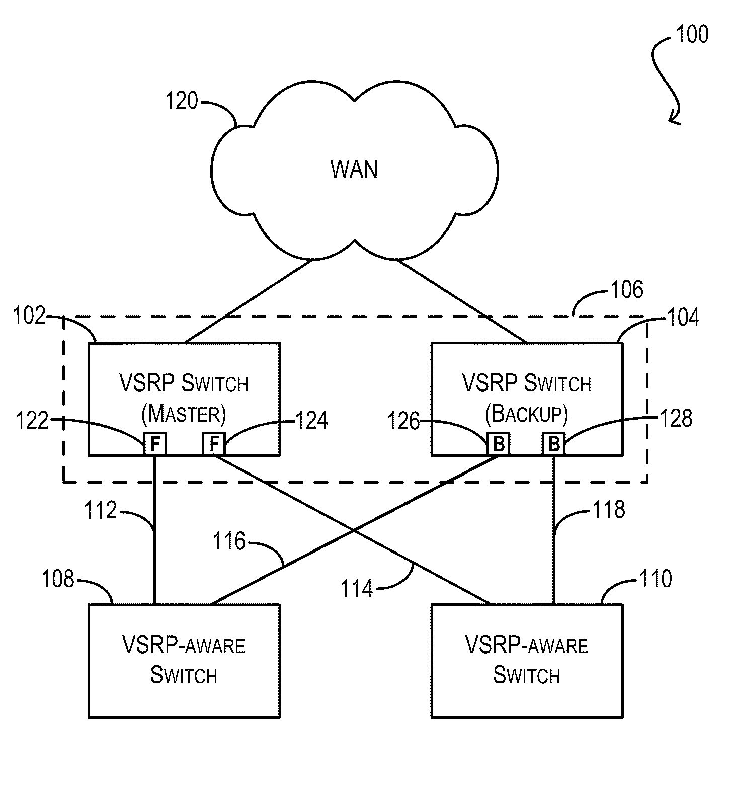
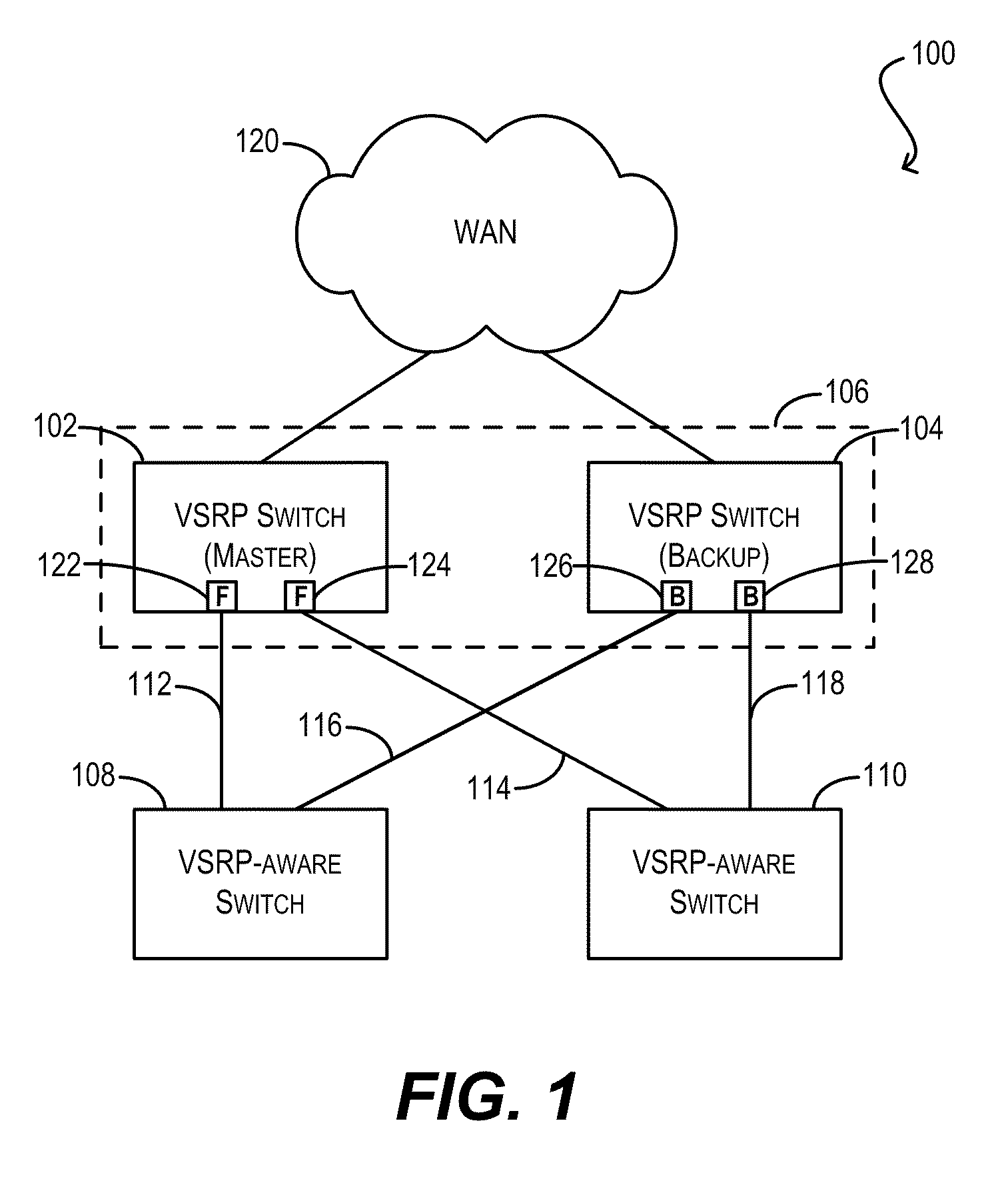
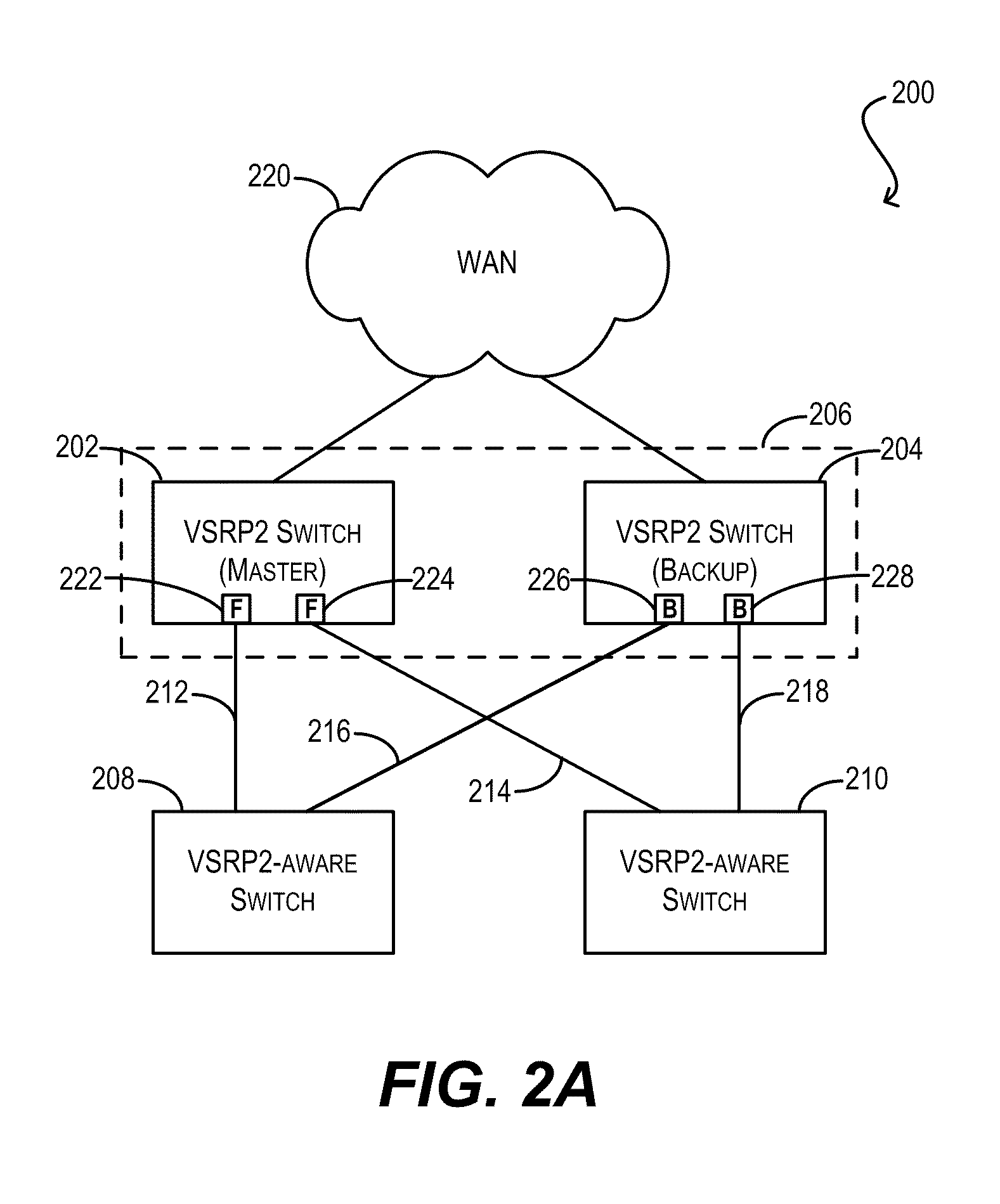
[0045]Embodiments of the present invention provide techniques for facilitating link redundancy in a loop-free Layer 2 network using an enhanced version of Virtual Switch Redundancy Protocol (VSRP), referred to herein as VSRP2. In one set of embodiments, a group of Layer 2 and / or Layer 2 / 3 devices (switches) can act in concert as a VSRP2 virtual switch. A first switch in the group (a VSRP2 master switch) can forward, via a first link, data traffic to / from a network device in a connected Layer 2 network. A second switch in the group (a VSRP2 backup switch) can block, at a second link, data traffic to / from the same network device. If the first link fails or otherwise becomes unavailable, the VSRP2 backup switch can d...
PUM
 Abstract
Description
Claims
Application Information