Apparatus and method for compensating polarization mode dispersion

a technology of polarization mode and compensator, applied in the field of fiber optic transmission systems, can solve the problems that the known feedback controlled optical pmd compensator (pmdc) for compensating for fiber pmd is not applicable to modulation formats using orthogonal polarization components, and the netlinear penalties are not applicable, so as to improve the signal to noise ratio of signals, improve the effect of signal to noise ratio, and easy averag

Active Publication Date: 2011-09-22
RPX CORP
View PDF4 Cites 9 Cited by
  • Summary
  • Abstract
  • Description
  • Claims
  • Application Information

AI Technical Summary

Benefits of technology

[0015]Preferably, the mixer can be adapted for multiplying the at least two electrical signal components to form the mixed electrical signals. Thus, fast multiplications of the electrical signal components can be performed before averaging the electrical signals. This improves the signal to noise ratio of the signals to be averaged and also of the feedback signal.
[0016]In a further embodiment the apparatus can comprise at least one rf power detector for averaging the electrical signal components and the mixed electrical signals to the average electrical signals and the average mixed electrical signals. Further the apparatus can comprise at least one analog-to-digital converter (ADC) for converting the average electrical signals into digital signals. Additionally, the apparatus can comprise a digital signal processor (DSP) for combining the digital signals to generate the feedback signal. With the rf power detectors the fast electrical signal at the output of the photo-diodes and after the mixers can be easily averaged to generate average signals with much lower bit rates as the original electrical signals. Through this, an incoming bit rate of for example 40 Gb / s can be easily transformed into a signal rate in the range of 1 Mb / s. As a result, cheap ADCs can be used, which can have a sampling rate much lower than the bit rate of the original optical signal. With the DSP, an simple calculation algorithm can be performed to generate the feedback signal from the slow digital signals coming from the ADCs.

Problems solved by technology

In highly dispersive pseudo-linear high bit-rate long-haul transmission systems, such as submarine or transcontinental terrestrial light wave transmission systems, intra-channel four-wave mixing (IFWM) and intra-channel cross-phase modulation (IXPM) are the main causes for nonlinear penalties.
Even worse, PMD is a statistical effect due to the environmental dependence of birefringence and mode-coupling of a single-mode fiber.
Known feedback controlled optical PMD compensators (PMDC) for compensating for fiber PMD are not applicable for modulation formats using orthogonal polarization components, i.e. APol or orthogonal multiplexing formats.

Method used


Image

  • Apparatus and method for compensating polarization mode dispersion
  • Apparatus and method for compensating polarization mode dispersion
  • Apparatus and method for compensating polarization mode dispersion

Examples


first embodiment

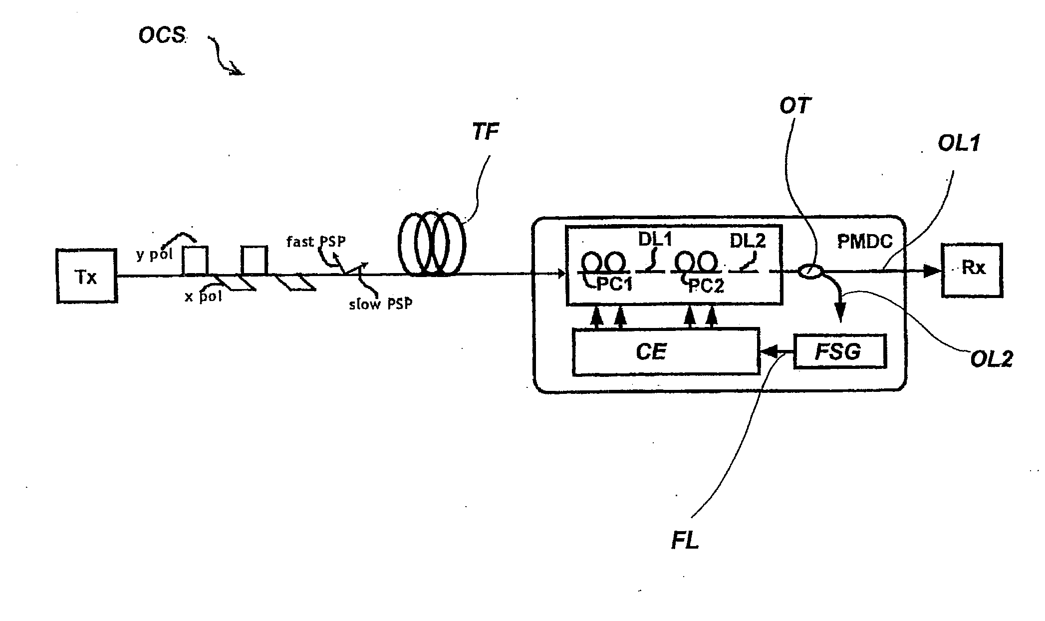
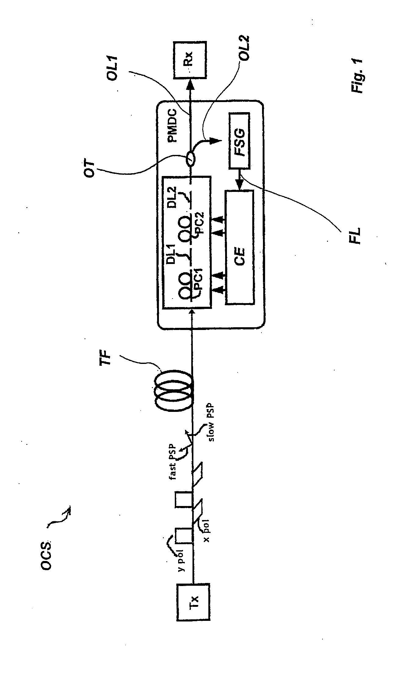
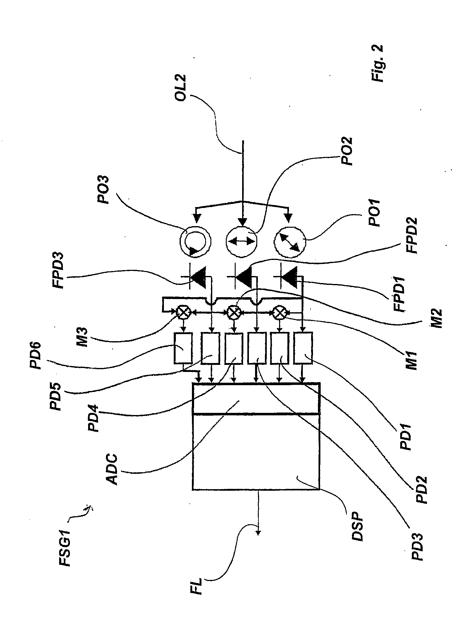
[0036]the feedback signal generator FSG is shown in FIG. 2 and designated there as FSG1.

[0037]The feedback signal generator FSG1 comprises three polarizers PO1, PO2 and PO3 for converting the extracted optical signal to three optical signal components with different defined states of polarization.

[0038]The polarizer PO1 converts the extracted optical signal to optical signal components of the state of + / −45° linear polarization. The polarizer PO2 converts the optical signal to the state of horizontal / vertical linear polarization, and the polarizer PO3 converts the optical signal to the state of left / right circular polarization.

[0039]The optical output of each polarizer PO1, PO2 and PO3 is connected to a respective fast photodiode FPD1, FPD2 and FPD3. The photodiodes FPD1, FPD2 and FPD3 are adapted for transforming the optical signal components into electrical rf power signal components, wherein each electrical signal component represents one of the defined states of polarization. In...

second embodiment

[0049]The diagram of FIG. 5 shows that the sum of the distances di, vertical axis named “sum di”, in the Poincaré sphere is dependent on the input polarization state of the PMDC, axis named “theta in rad”, and the fiber DGD, axis named “DGD in ps”. The distance di is monotonically decreasing in the region of low fiber DGD, which means low distortion from the fiber PMD, and hence fulfills the requirement for a feedback signal. For compensating the fiber PMD, a suitable feedback routine can minimize the sum of the distances di for minimizing the DGD. Exemplary feedback routines stated below can be performed by the above described feedback signal generators FSG; FSG1 or a feedback signal generator FSG2, shown in FIG. 6, which is described below. The control electronics CE can adapt the first-stage polarization converter PC1 and the second-stage polarization converter PC2 such, that the feedback signal is minimized to reduce the DGD ideally to zero.

[0050]For compensating the fiber PMD e...


PUM


Abstract

An apparatus (PMDC) for compensating polarization mode dispersion for an optical transmission fiber (TF) for transmission of optical signals, said optical signals having a first polarization component (x pol) and a orthogonal second polarization component (y pol) comprises tuneable means (PC1, DL1, PC2, DL2) adapted to compensating said fiber polarization mode dispersion. It further comprises a feedback signal generator (FSG) adapted to generating a feedback input signal for said tuneable means (PC1, DL1, PC2, DL2) for polarization mode dispersion compensation. Said feedback signal generator (FSG) comprises polarization means for converting said transmitted optical signal to at least two optical signal components with different defined states of polarization. It has further transforming means for transforming said optical signal components into electrical signal components, wherein each electrical signal component representing one of said defined states of polarization. At least one mixer is earmarked for mixing at least two of said electrical signal components to mixed electrical signals. Means are intended for averaging said electrical signal components to average electrical signals and averaging said mixed electrical signals to average mixed electrical signals. Further means are destined for combining said average electrical signals and said average mixed electrical signals to generate said feedback input signal which is characteristic for a digital group delay of said transmission signal caused by said polarization mode dispersion.

Description

FIELD OF THE INVENTION[0001]The invention relates to fiber optic transmission systems, and more particularly to an apparatus and a method for compensating polarization mode dispersion introduced by an optical transmission fiber when transmitting optical signals. The optical signals have a first polarization component and an orthogonal second polarization component.BACKGROUND OF THE INVENTION[0002]In highly dispersive pseudo-linear high bit-rate long-haul transmission systems, such as submarine or transcontinental terrestrial light wave transmission systems, intra-channel four-wave mixing (IFWM) and intra-channel cross-phase modulation (IXPM) are the main causes for nonlinear penalties. Use of a differential-phase-shift-keying (DPSK) modulation format can mitigate these penalties as compared to on-off-keying (OOK). It has also been shown that the reduced pulse energy of Return-to-Zero (RZ)-DPSK compared to RZ-OOK and a correlation between the nonlinear phase shifts of two adjacent pu...

Claims


Application Information

Patent Timeline
Patent Type & Authority Applications(United States)
IPC IPC(8): H04B10/18H04B10/2569
CPCH04B10/2569G02B6/278
Inventor BUELOW, HENNINGJAEGER, PIERRE
Owner RPX CORP
Why Eureka
Try Eureka