Caster

a caster and caster body technology, applied in the field of casters, can solve the problems of needing more force when moving a thing, and the caster cannot move in a backward direction, and achieve the effect of improving a straight movement, easy matching, and easy changing the direction of the thing

Inactive Publication Date: 2011-09-29
LEE SEUNG YOUL
View PDF7 Cites 11 Cited by
  • Summary
  • Abstract
  • Description
  • Claims
  • Application Information

AI Technical Summary

Benefits of technology

[0032]According to the present invention, the rotation body can rotate 360° about the first rotary shaft, and the frame, which supports the wheels, can rotate 360° about the rotation body and the first rotary shaft which is installed at a plate on which a thing to be moved is positioned, so that it is possible for the plate, which supports the first rotary shaft, to rotate about the rotation body, which makes it possible to easily change the direction of the thing to be moved or transported. Since 360° rotation can be possible in place, a direction change can be performed in a narrow space.
[0033]Since the rotation body or frame can be installed at an inclined angle the arrangement of the wheels can be easily matched with the traveling direction for thereby improving a straight movement in one direction.
[0034]In addition, it is possible to obtain a desired straight movement by limiting the rotation angle of the frame which supports the wheel rotary shaft. Since the rotation range of the frame can be limited not to exceed 180° in the traveling direction, the decrease of the straight movement due to unnecessary rotation can be prevented while not interfering with the straight movement in the traveling direction.
[0035]When a large force is needed for movement in a still state because the weight of the thing to be moved is too large, the thing to be moved can be swung in left and right directions for thereby decreasing a friction coefficient on the contact surface between the wheels and floor, so it can be moved with a smaller force. Namely, the caster provides a pulley function among the first rotary shaft, the rotation body and the frame which supports the wheel rotary shaft.
[0036]The distance between the wheel rotary shaft and the second rotary shaft is larger than the distance between the first rotary shaft and the second rotary shaft, so one direction movement can be enhanced. In addition, the distance between the wheel rotary shaft and the second rotary shaft might be less than the distance between the first rotary shaft and the second rotary shaft. In this case, the rotational force can be enhanced, which results in an easier direction change. So the length of the frame including the wheel rotary shaft can change depending on the function and characteristic of the product to be applied to the caster.
[0037]Since a user can fix the rotation body to the plate by using a locking unit, the straight movement can be optimized when moving a remote distance.

Problems solved by technology

However the caster with two rotary shafts happens to roll randomly when it loose a balance of force applied to itself, so the caster can't move in a desired direction, which leads to needing more force when moving a thing.
However when the rotary shaft of the caster is engaged to a lower side and a slope surface of a plate which is to move a thing, the caster cannot move in a backward direction due to its inherent physical limitation, and a lot of spaces is needed so that the plate can move over 90°.

Method used


Image

  • Caster
  • Caster
  • Caster

Examples


Embodiment Construction

[0046]The caster according to a preferred embodiment of the present invention will be described with reference to the accompanying drawings.

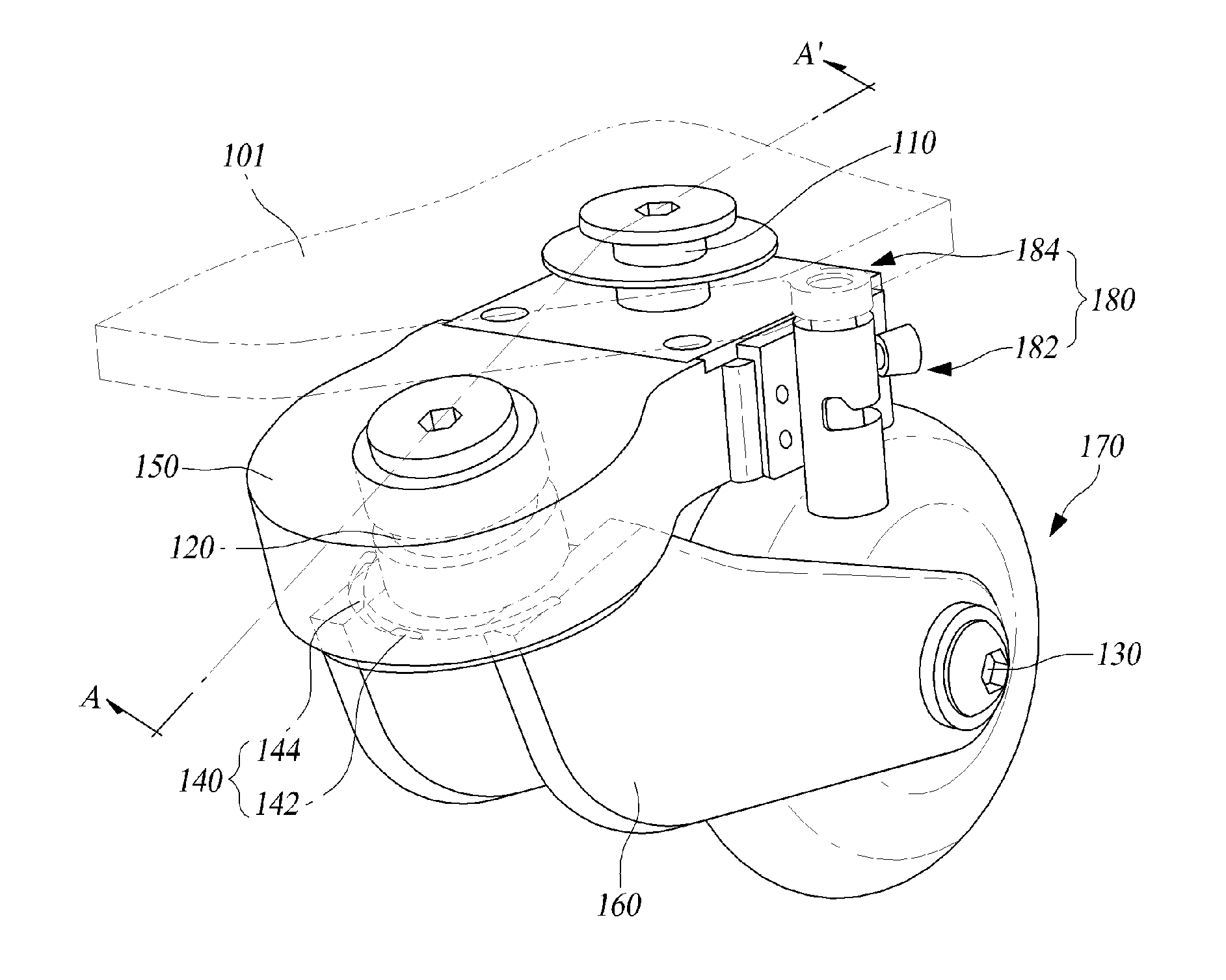
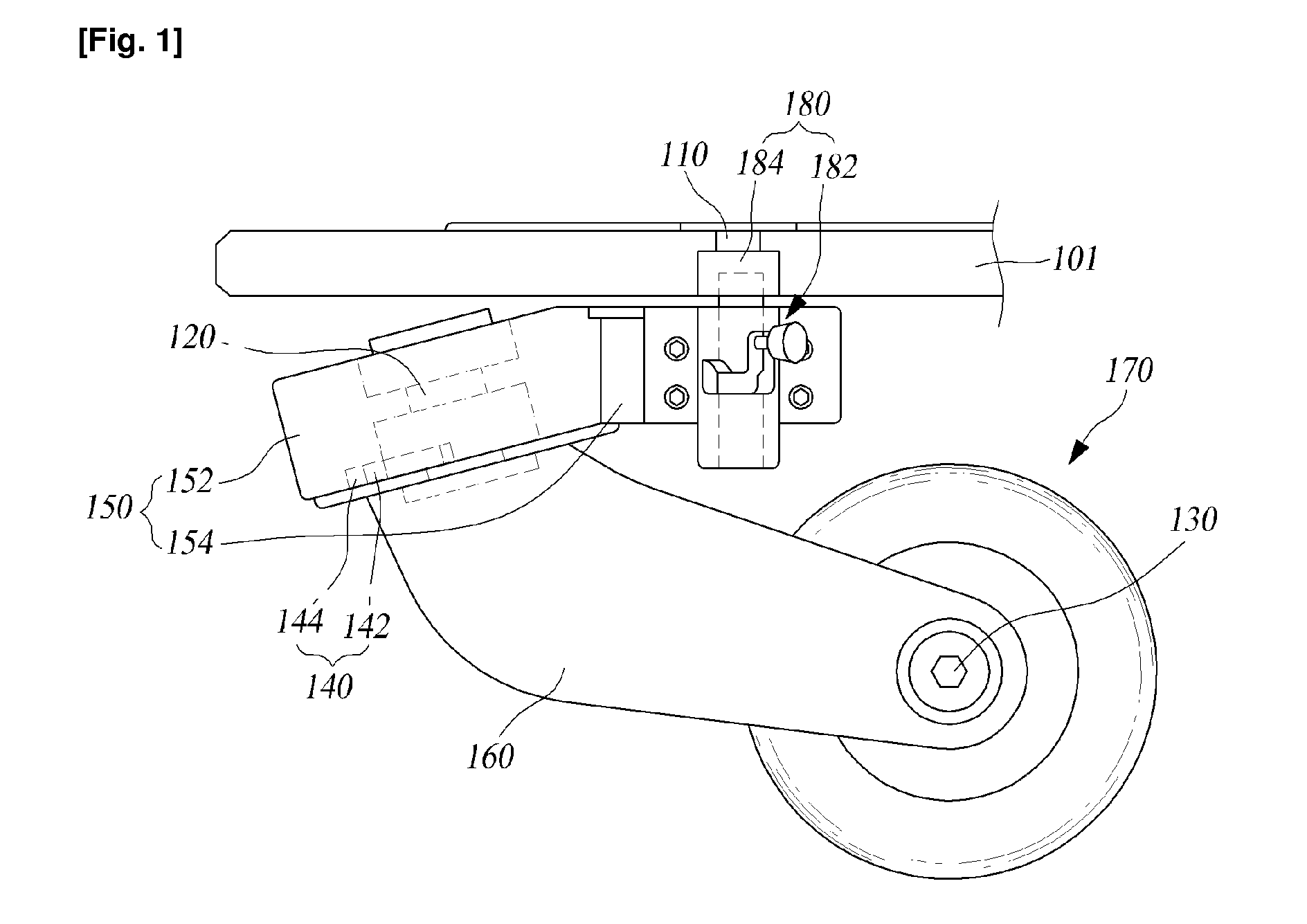
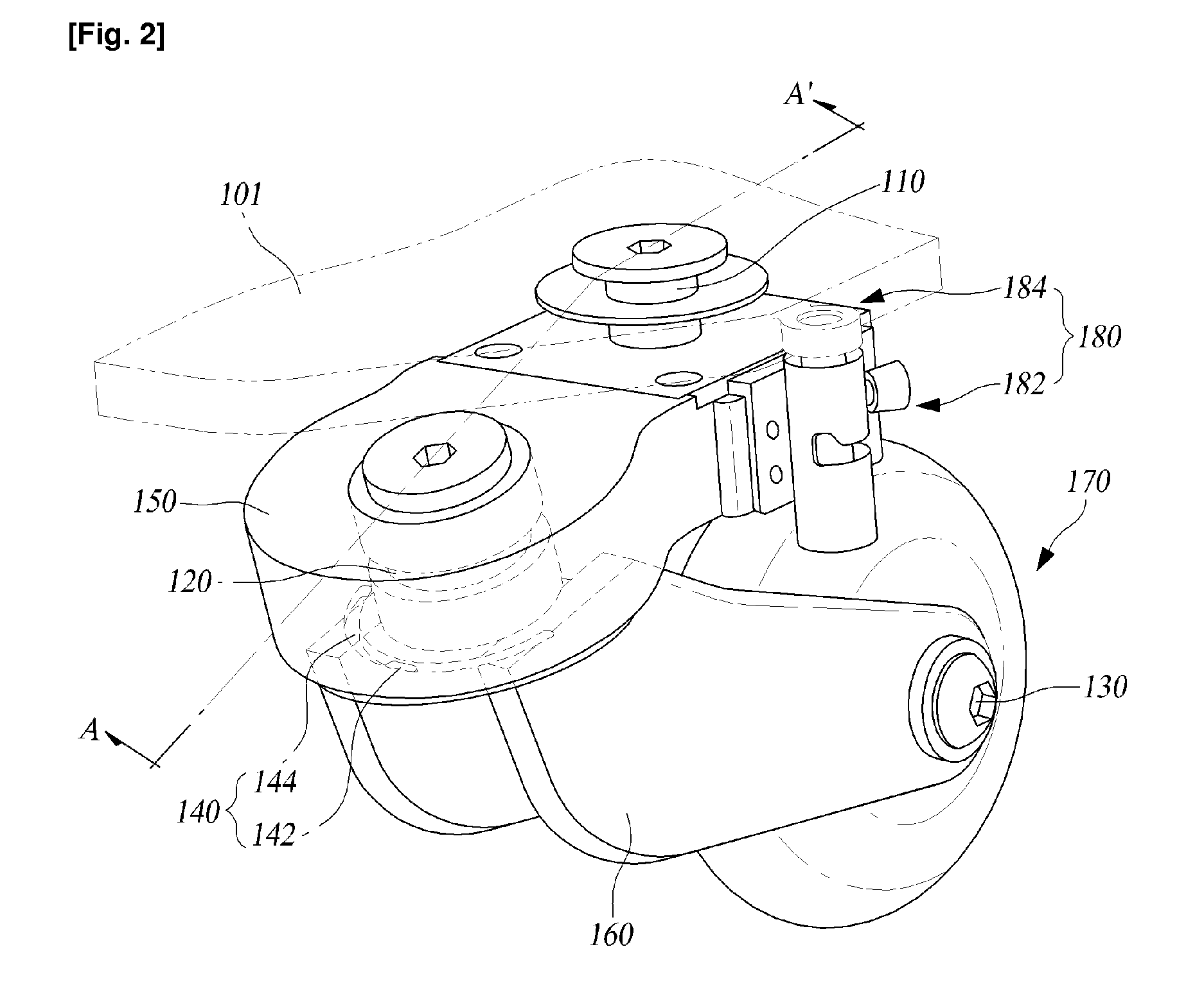
[0047]FIG. 1 is a front view of a caster according to an embodiment of the present invention, and FIG. 2 is a perspective view illustrating a caster according to an embodiment of the present invention, and FIG. 3 is a cross sectional view illustrating a cross section profile cut along A-A′ of FIG. 2. As shown in FIGS. 1 to 3, the caster according to the present invention comprises a first rotary shaft 110, a second rotary shaft 120, a rotation body 150, a frame 160, a wheel rotary shaft 130 and a wheel 170.

[0048]The first rotary shaft 110 is installed on the plate 101 on which a thing to be moved is placed. The rotation body 150 is rotatably engaged to the first rotary shaft 110. The upper side of the first rotary shaft 110 is fixed to the lower surface of the plate 101. The rotation body 150 is engaged to a lower side of the first rotary shaft ...


PUM


Abstract

A caster for moving a thing is disclosed. The caster comprises a first rotary shaft which is installed at a plate on which a thing to be moved is positioned; a rotation body of which one portion is rotatably engaged to the first rotary shaft; a frame of which an upper side is rotatably connected to the other portion of the rotation body; and a wheel which is rotatably installed at a lower side of the frame.

Description

TECHNICAL FIELD[0001]The present invention relates to a caster which is used to move a thing, and in particular to a caster which makes it possible to move a thing with the aid of a combination of a rotation body, first and second rotary shafts connected with the rotation body and a wheel rotary shaft, so the caster according to the present invention can rotate or move straight in any direction that a user wants.BACKGROUND ART[0002]A conventional caster is formed of one rotary shaft or two rotary shafts. In case of a caster with one rotary shaft, since it is directed to driving only wheels, the caster is designed to move in either a forward direction or a backward direction.[0003]In case of a caster with two rotary shafts for an easier direction change, one rotary shaft is mounted on a frame which supports wheel rotary shafts, and the rotary shaft is in parallel engaged to a lower side of a plate that will move a thing, so the frame, which supports the wheel rotary shafts, can rotat...

Claims


Application Information

Patent Timeline
Patent Type & Authority Applications(United States)
IPC IPC(8): B60B33/00
CPCB60B33/0002B60B33/0007B60B33/0015B60B33/0021B60B33/0039Y10T16/184B60B33/0057B60B33/0068B60B33/0071B60B33/0073B60B33/0049
Inventor LEE, SEUNG YOUL
Owner LEE SEUNG YOUL
Why Eureka
Try Eureka