
Chain Saw

a chain saw and chain saw technology, applied in the field of chain saws, can solve the problems of undamaged studs and nuts including their outer and inner threads, and achieve the effects of avoiding additional components, ensuring reliable clamping, and effective structur

Active Publication Date: 2011-09-29
ANDREAS STIHL AG & CO KG
View PDF7 Cites 29 Cited by
  • Summary
  • Abstract
  • Description
  • Claims
  • Application Information

AI Technical Summary

Benefits of technology

[0007]It is an object of the invention to provide a chain saw of the type described above wherein the sprocket wheel cover can also be applied and screwed down without any danger of overstressing the arrangement when the guide bar has been removed.

Problems solved by technology

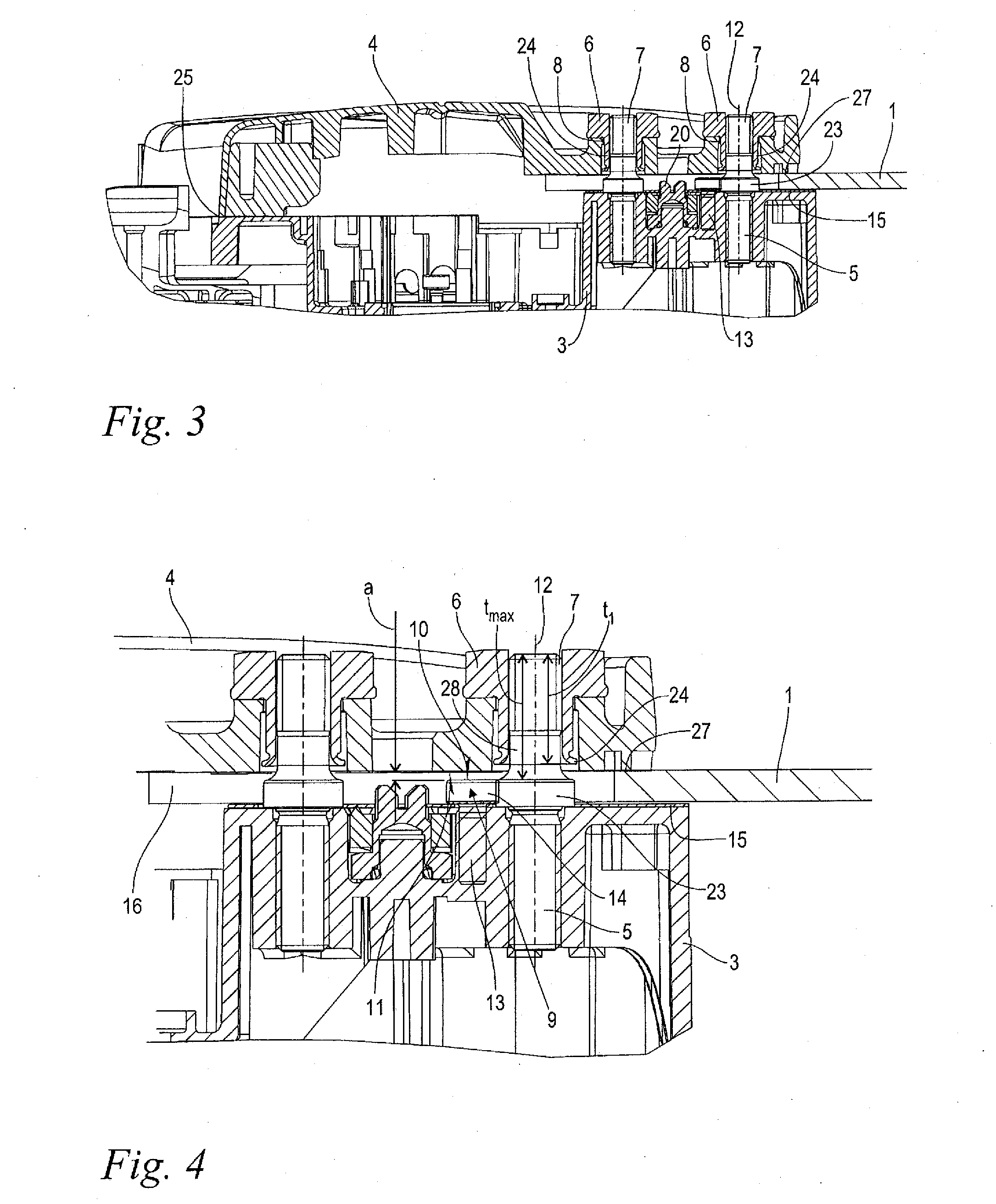
In fact, the maximum usable screw-in depth is larger than the stop screw-in depth, so that the studs and the nut including their outer and inner threads remain undamaged.

Method used


Image

  • Chain Saw
  • Chain Saw
  • Chain Saw

Examples


Embodiment Construction

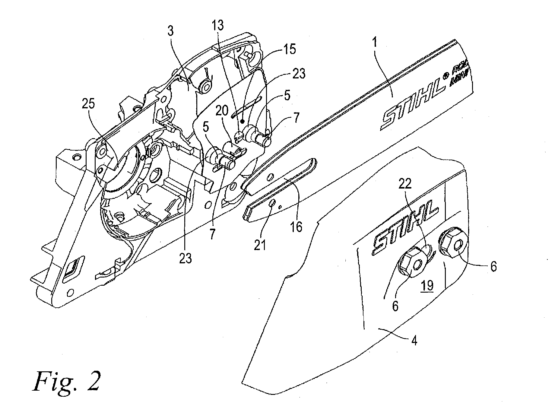
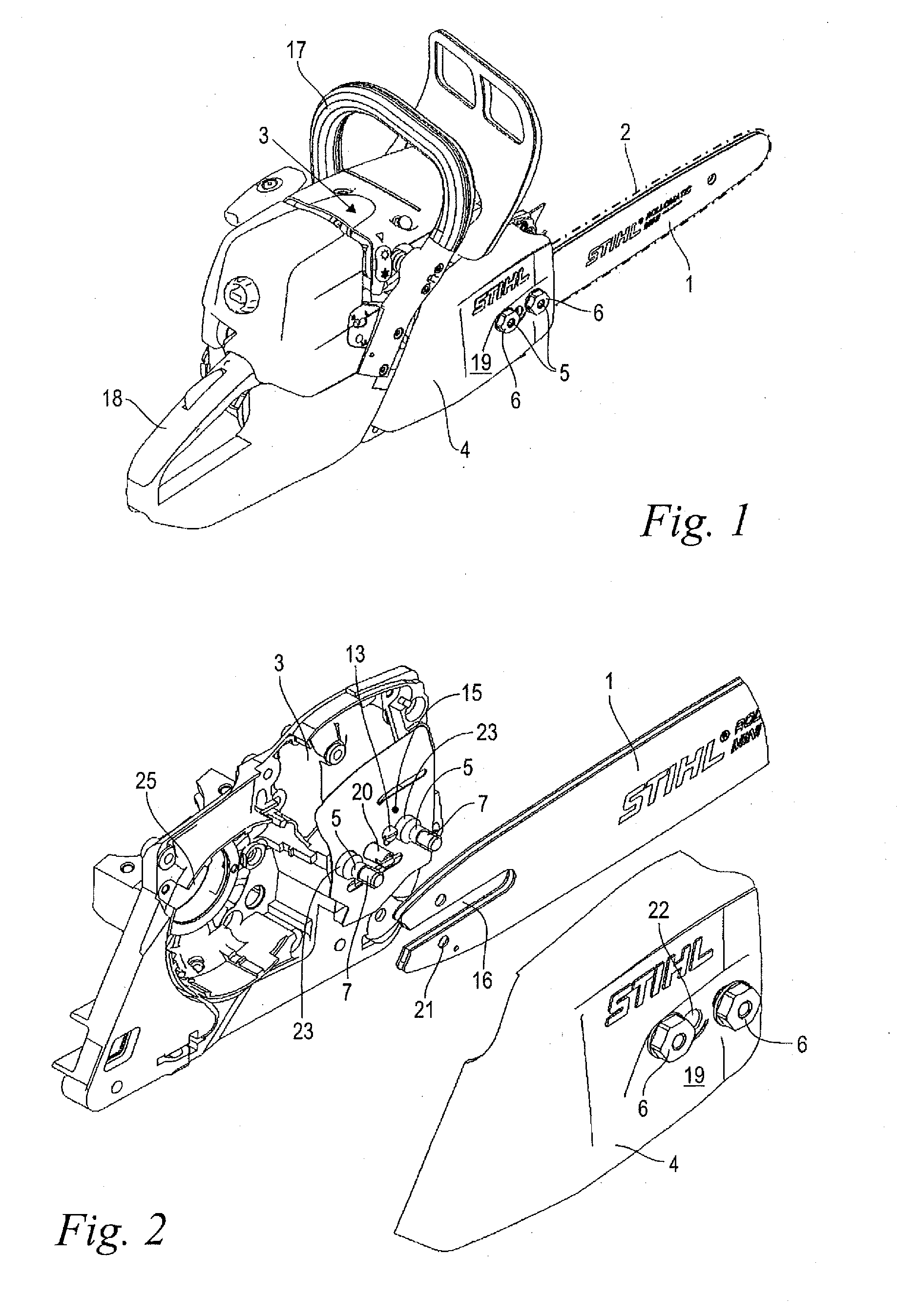
[0025]FIG. 1 shows a handheld, motor-driven chain saw. The chain saw includes a housing 3 in which a drive motor, not shown, is arranged. In the shown embodiment, the drive motor is a two-stroke combustion engine but can also be a four-stroke engine. An electric motor can also be provided in place of the combustion engine. A guide bar 1 protruding forwards from the housing 3, in relation to the usual operating position, is arranged laterally of the housing 3. A saw chain 2 driven by the drive motor is circulatingly guided about the outer edge of the guide bar 1. A front handle 17 is arranged toward the center above the housing 3. A back handle 18 is provided on the rear end of the housing 3 which is opposite to the guide bar 1. The chain saw is carried and guided by hand via the handles (17, 18) during operation.

[0026]The drive motor drives a sprocket wheel, not shown, whose external teeth engage between the links of the saw chain 2 and thus set the saw chain 2 in motion. The sprock...


PUM

PropertyMeasurementUnit
Lengthaaaaaaaaaa
Distanceaaaaaaaaaa
Distanceaaaaaaaaaa

Abstract

A chain saw includes a guide bar (1) for a saw chain, a housing (3), a sprocket wheel cover (4), and at least one stud (5) fixed on the housing (3) for threadably fastening the sprocket wheel cover (4) and the guide bar (1). The free thread end (7) of the stud (5) has a maximum usable screw-in depth (tmax) for a nut (6) to be screwed thereon. A stop (9) for the sprocket wheel cover (4) having a stop surface (10) as well as a support surface (11) for contact engaging the stop surface (10) are provided. In the mounted state of the guide bar (1), a distance (a) remains between the stop surface (10) and the support surface (11). The support surface (11) contact engages the stop surface (10) of the stop (9) when the guide bar (1) is removed and the nut (6) is tightened and the nut (6) is screwed onto the studs (5) with a stop screw-in depth. The stop (9) is configured in such a manner that the maximum usable screw-in depth (tmax) is greater than the stop screw-in depth.

Description

CROSS REFERENCE TO RELATED APPLICATION[0001]This application claims priority of German patent application no. 10 2010 012 748.5, filed Mar. 25, 2010, the entire content of which is incorporated herein by reference.BACKGROUND OF THE INVENTION[0002]Handheld chain saws include a saw chain which revolves around the periphery of a guide bar. To drive the saw chain, a sprocket wheel having an externally toothed gear, which is driven by a drive motor, is provided. The external teeth of the sprocket wheel engage between the members of the saw chain and drive them.[0003]The drive shaft of the sprocket wheel is mounted in a housing of the chain saw. A sprocket wheel cover which covers the area of the sprocket wheel is threadably engaged with the housing. At least one stud, which in its mounted state is guided through an opening of the sprocket wheel cover, is fixed to the housing for the threaded fastening. A nut is screwed onto a free thread end of the stud and presses the sprocket wheel cov...

Claims


Application Information

Patent Timeline
IPC IPC(8): B27B17/02
CPCB27B17/02
Inventor WOLF, GUNTEREBERHARDT, MAXIMILIANWEISSERT, WOLFGANG
Owner ANDREAS STIHL AG & CO KG
Learn More