
Simplified variable geometry turbocharger with variable nozzle

a turbocharger and variable nozzle technology, applied in the direction of machines/engines, stators, liquid fuel engines, etc., can solve the problems of limiting the boost level of the engine, affecting the critical pressure ratio at which the valve opens, and its turbine power control characteristics are rudimentary and coarse, etc., to achieve modulation of the boost pressure of the turbocharger, low cost, and low cost

Inactive Publication Date: 2011-09-29
BORGWARNER INC
View PDF14 Cites 18 Cited by
  • Summary
  • Abstract
  • Description
  • Claims
  • Application Information

AI Technical Summary

Benefits of technology

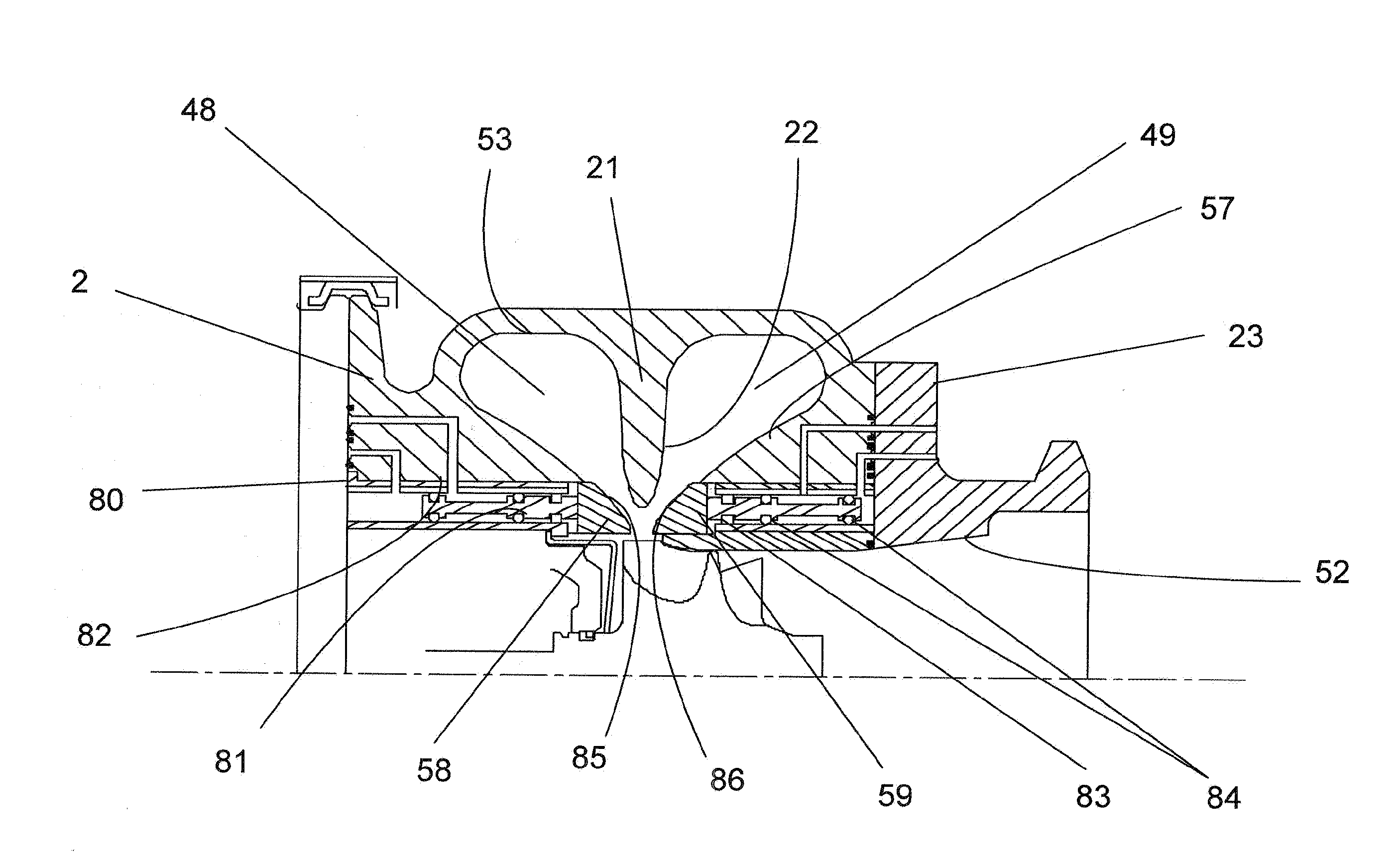
[0027]The present invention relates to a simplified, low cost, variable nozzle to control exhaust gas flow to a turbine wheel in a variable flow turbocharger. The boost pressure can be modulated by controlling the nozzle flow volume. The invention is based on the idea that flow path of exhaust gas to the turbine wheel (70) of a twin volute turbocharger is influenced by the shape and size of the nozzle formed by the shape (22) of the divider wall (21) and the shape of the flow passage determined by the walls (85, 86) of the turbine housing. By moving the walls (85, 86) toward, or away from the divider wall, the flow of exhaust gas through the nozzle, to the turbine wheel (70) can be modulated, which thus modulates the turbocharger boost pressure. In another embodiment, the nozzle formed by these walls and the divider wall is changed by rotating cylinders (58, 59) containing these walls such that the gap to the divider wall is changed, modulating the exhaust flow to the turbine wheel (70) and thus modulating the boost pressure. In yet another embodiment, the divider wall is constructed as a separate component, with the inner tip of the divider wail designed as a spiral, changing the “tip-to-tip” ratio to the turbine wheel at given sections. Rotation of the spiral divider wall changes the nozzle width as described above to modulate the turbine flow and thus boost pressure. The invention also applies to single volute turbines.

Problems solved by technology

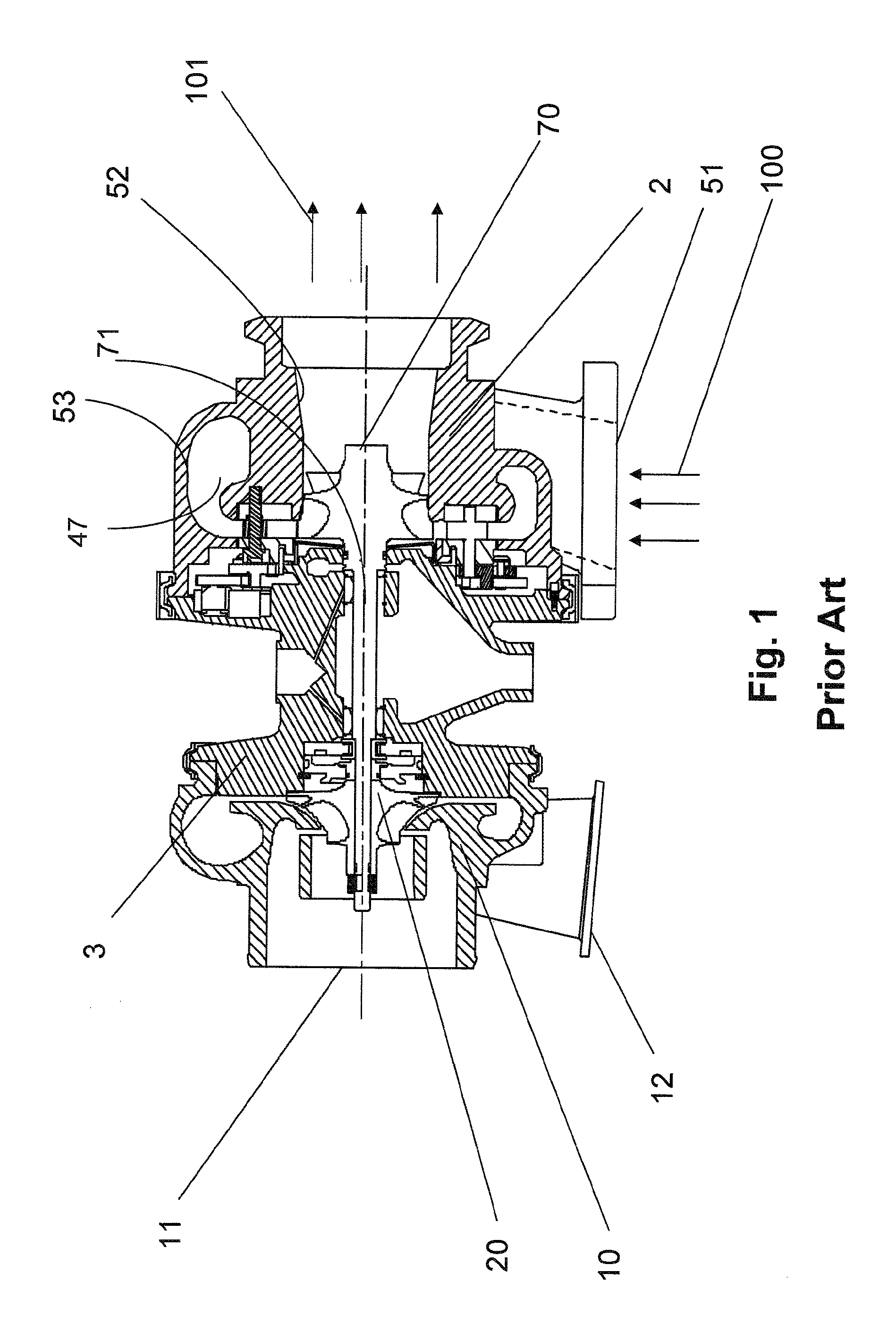
These requirements often result in compromises such as architectural requirements outside of the turbine housing, method of location and mounting of the turbine housing to the bearing housing, and the transition from slice “A” to the turbine foot (51) result in turbine housing volutes of rectangular or triangular section, as well as in circular, or combinations of all shapes.
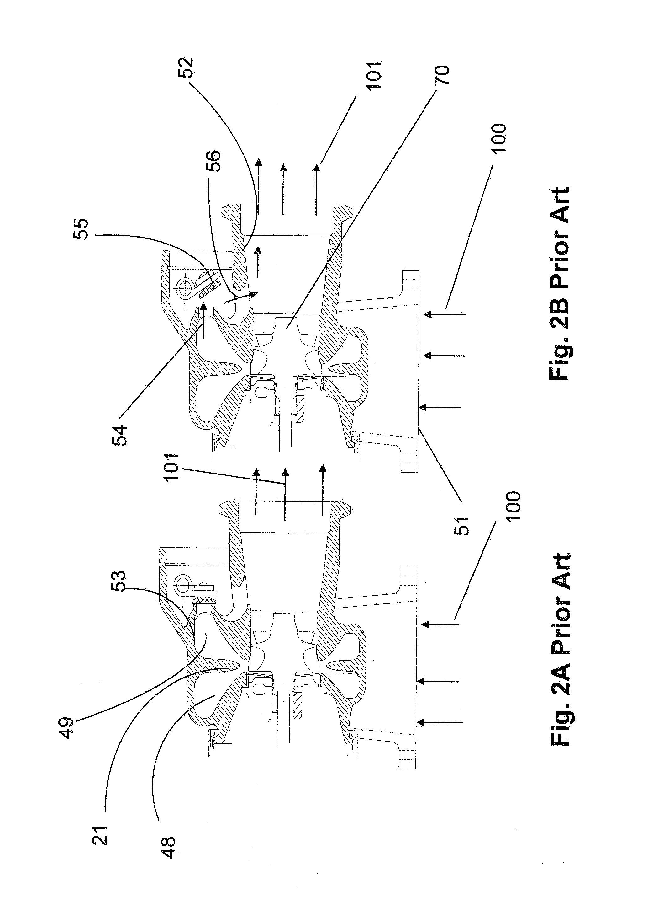
The function of the wastegate valve, in this manner, is to cut the top off the full load boost curve, thus limiting the boost level to the engine.
While a wastegate can be used to limit boost levels, its turbine power control characteristics are rudimentary and coarse.
If the wastegated turbocharger has a “dumb” actuator, which operates on a pressure or vacuum signal only, and is operated at altitude, then the critical pressure ratio at which the valve opens is detrimentally affected.
Since the diaphragm in the actuator senses boost pressure on one side, and barometric pressure on the other, the tendency is for the actuator to open later (since the barometric pressure at altitude is lower than that at sea level) resulting in over-boost of the engine.
The problem is that most wastegates are somewhat binary in their operation, which does not fit well with the linear relationship between engine output and engine speed.
These are very expensive to procure, machine, and weld (where required).
This translates to expensive actuators.
While VTGs of various types and configurations have been adopted widely to control both turbocharger boost levels and turbine backpressure levels, the cost of the hardware and the cost of implementation are high.

Method used


Image

  • Simplified variable geometry turbocharger with variable nozzle
  • Simplified variable geometry turbocharger with variable nozzle
  • Simplified variable geometry turbocharger with variable nozzle

Examples


third embodiment

this invention involves the same aerodynamic adjustment of the nozzle but in a more complex manner.

[0055]Since the distance from the tip of the divider wall to the tip of the turbine wheel, (FIG. 13“T”) often referred to as the “tip-to-tip” ratio, is critical to performance, the tip to tip ratio should be kept to no less than 106% of the turbine wheel diameter for blade excitation reasons, and no more than 106% for efficiency reasons. In FIG. 13, for a turbine wheel diameter of “R” the ratio would be:

(“R”+”T”)”R”

With a cast divider wall, in a cast turbine housing, the dross generated by the casting process is driven to the tip of the thin divider wall which produces an undesirable material composition at the tip of the divider wall. This low quality material has a tendency to prematurely fatigue and fall out of the divider wall into the turbine wheel, damaging the turbine wheel. To prevent this occurrence, the divider walls are cast thicker than would be aerodynamically desired, and...


PUM


Abstract

The flow path of exhaust gas to the turbine wheel (70) of a twin volute turbocharger is influenced by the shape and size of the nozzle formed by the shape (22) of the divider wall (21) and the shape of the flow passage determined by the walls (85, 86) of the turbine housing. By moving the walls (85, 86) toward, or away from the divider wall, the flow of exhaust gas through the nozzle, to the turbine wheel (70) can be modulated, which thus modulates the turbocharger boost pressure. The invention also applies to single volute turbines.

Description

FIELD OF THE INVENTION[0001]This invention relates to a simplified, low cost, variable nozzle to control exhaust gas flow to a turbine wheel in a variable flow turbocharger. Thus boost pressure can be modulated by controlling the nozzle flow volume. More particularly, the invention provides a variable nozzle turbocharger which produces change of turbine flow with acceptable resolution, at a cost lower than that for a VTG turbocharger. By altering the nozzle volume between the divider wall and the contour, the turbine flow to the turbine wheel can be modulated, and thus the boost level output of the turbocharger may also be modulated.BACKGROUND OF THE INVENTION[0002]Turbochargers are a type of forced induction system. They deliver air, at greater density than would be possible in the normally aspirated configuration, to the engine intake, allowing more fuel to be combusted, thus boosting the engine's horsepower without significantly increasing engine weight. This can enable the use o...

Claims


Application Information

Patent Timeline
Patent Type & Authority Applications(United States)
IPC IPC(8): F02B37/22F04D29/40F02B37/00
CPCF01D9/026F01D17/143F02B37/025F05D2220/40F02C6/12Y02T10/144F02B37/22Y02T10/12
Inventor ANSCHEL, PAULCHANDRAMOHANAN, RAJMOHAN
Owner BORGWARNER INC
Learn More