Simplified variable geometry turbocharger with vane rings

a variable geometry, turbocharger technology, applied in the direction of machines/engines, stators, liquid fuel engines, etc., can solve the problems of limiting the boost level of the engine, the critical pressure ratio at which the valve opens is detrimentally affected, and the turbine power control characteristics are rudimentary and coarse, so as to achieve low cost and modulate the boost pressure

Inactive Publication Date: 2011-10-06
BORGWARNER INC
View PDF5 Cites 24 Cited by
  • Summary
  • Abstract
  • Description
  • Claims
  • Application Information

AI Technical Summary

Benefits of technology

[0026]The present invention relates to a simplified, low cost, variable nozzle to control the exhaust gas flow to a tu...

Problems solved by technology

These requirements often result in compromises such as architectural requirements outside of the turbine housing, method of location and mounting of the turbine housing to the bearing housing, and the transition from slice “A” to the turbine foot (51) result in turbine housing volutes of rectangular or triangular section, as well as in circular, or combinations of all shapes.
The function of the wastegate valve, in this manner, is to cut the top off the full load boost curve, thus limiting the boost level to the engine.
While a wastegate can be used to limit boost levels, its turbine power control characteristics are rudimentary and coarse.
If the wastegated turbocharger has a “dumb” actuator, which operates on a pressure or vacuum signal only, and is operated at altitude, then the critical pressure ra...

Method used


Image

  • Simplified variable geometry turbocharger with vane rings
  • Simplified variable geometry turbocharger with vane rings
  • Simplified variable geometry turbocharger with vane rings

Examples


first embodiment

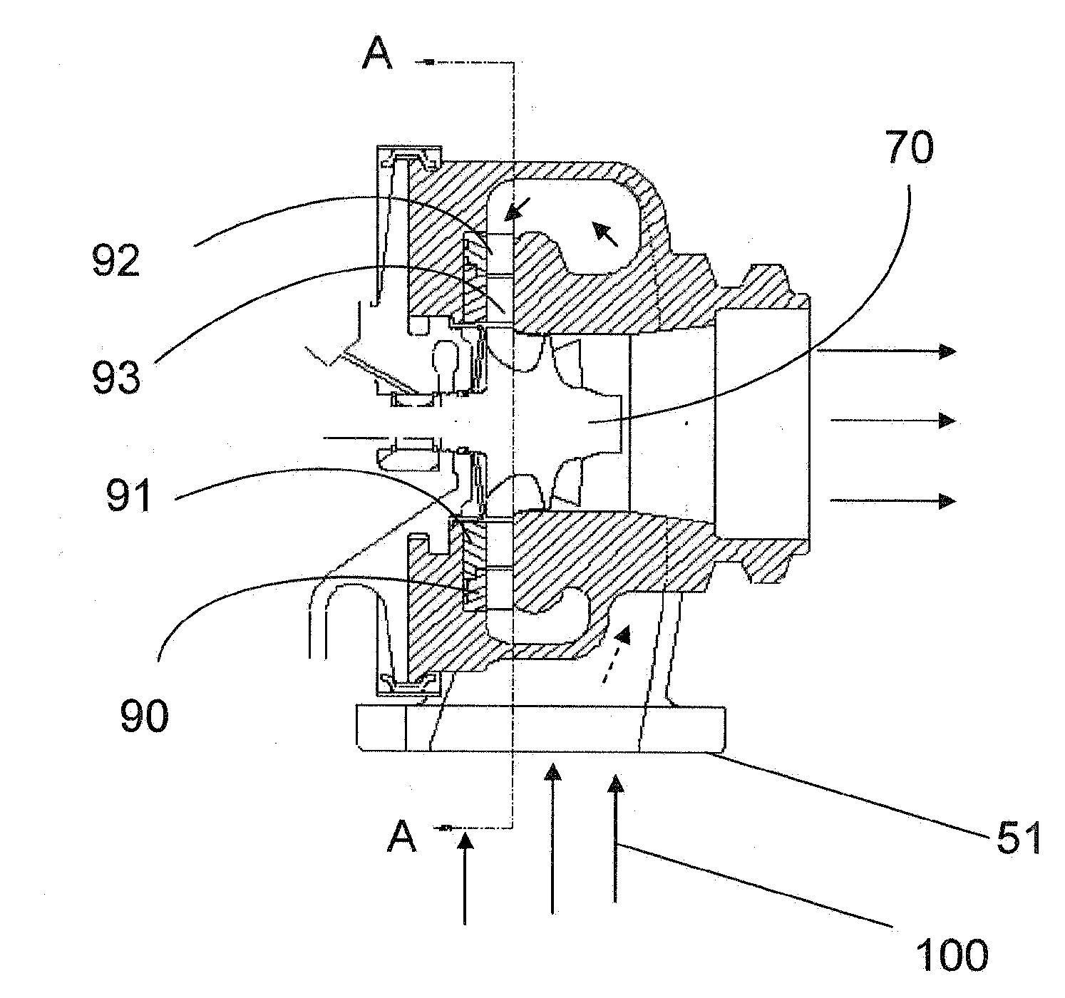
[0046]In the first embodiment, shown in FIGS. 8A, 8B, 9A and 9B, a plurality of vane shapes (92) are arranged on an outer vane ring (90) such that these vanes present a leading edge (94) of a vane shape to the incoming exhaust airflow (102), turning the airflow from the volute to a direction (103) aimed at the vortex of the turbine wheel. On an inner vane ring (91), a plurality of vane shapes (93) are arranged such that these vanes present the trailing part of the leading vane shape, arranged on the outer vane ring, to “pinch” the flow of exhaust gas and thereby further guide and influence the flow direction of the exhaust gas coming from the arrangement on the outer vane ring.

[0047]To alter the flow of exhaust gas from the volute to the turbine wheel, the relative circumferential position of the vane rings, with respect to each other, is changed. This change can be effected by rotating the outer vane ring, with the inner vane ring stationary; by rotating the inner vane ring, with t...

second embodiment

[0052]The design of the vanes in the second embodiment is such that circumferential displacement of one of the vane rings, with respect to the other vane ring, or with respect to the turbine housing or bearing housing, for cases in which the vanes on the non-rotational vane ring are fabricated onto the sidewall of either the turbine housing or bearing housing.

[0053]This circumferential displacement of one vane ring causes motion on the other vane ring such that a vane, mounted so that it can rotate about an axis (120) parallel to the turbocharger centerline, rotates about said axis (120) to modify the flow volume to the turbine wheel.

[0054]In FIG. 12A and FIG. 12B the vanes are arranged such that the outer vane ring (90) moves in a circumferential motion (96). The circumferential displacement of the outer vane (90) to the inner vane ring (91) causes the tongues (126) on the vanes (122) to rotate the vanes (121) on the lower vane ring (91) about the axes (120) so the vanes effective ...


PUM


Abstract

The flow path of exhaust gas to the turbine wheel (70) of a turbocharger is influenced by relative motion between two rings of vanes, at least one of which being provided on a vane ring. The outer ring of vanes contains a plurality of vanes (92, 122), the inner ring of vanes contains a plurality of vanes (93, 121), and the inner and outer vanes in registry forming a single generic vane shape. The aerodynamic effect of relative displacement of the outer ring of vanes to the inner ring of vanes produces a modulate-able control of exhaust flow to the turbine wheel.

Description

FIELD OF THE INVENTION[0001]This invention is directed to the design of a low cost turbine flow control device.BACKGROUND OF THE INVENTION[0002]Turbochargers are a type of forced induction system. They deliver air, at greater density than would be possible in the normally aspirated configuration, to the engine intake, allowing more fuel to be combusted, thus boosting the engine's horsepower without significantly increasing engine weight. This can enable the use of a smaller turbocharged engine, replacing a normally aspirated engine of a larger physical size, thus reducing the mass and aerodynamic frontal area of the vehicle.[0003]Turbochargers (FIG. 1) use the exhaust flow (100), which enters the turbine housing at the turbine inlet (51) of the turbine housing (2), from the engine exhaust manifold to drive a turbine wheel (70), which is located in the turbine housing. The turbine wheel is solidly affixed to a shaft, the other end of which contains a compressor wheel which is mounted...

Claims


Application Information

Patent Timeline
IPC IPC(8): F04D29/44
CPCF01D17/165F01D17/167F05D2220/40F02C6/12F02B37/24F01D17/16F02B37/22F02B39/00
Inventor ALAJBEGOVIC, VAHIDINJENKS, GORDON
Owner BORGWARNER INC
Why Eureka
Try Eureka