Eureka AIR delivers breakthrough ideas for toughest innovation challenges, trusted by R&D personnel around the world.

Complex reduction mechanism of linear actuator

Inactive Publication Date: 2011-09-29
HIWIN MIKROSYST
View PDF1 Cites 9 Cited by
  • Summary
  • Abstract
  • Description
  • Claims
  • Application Information

AI Technical Summary

Benefits of technology

[0008]To achieve the above and other objects, the complex reduction mechanism of the linear actuator of the present invention is installed in the linear actuator between a power source and an actuation shaft of the linear actuator. The complex reduction mechanism serves to reduce the rotational speed output from the power source and transmit the rotational power of the power source to the actuation shaft for driving the actuation shaft to linearly axially move. The complex reduction mechanism includes: a primary reducing unit including a primary input shaft, a primary output shaft and a primary reducing set positioned between the primary input shaft and the primary output shaft, the primary input shaft being coupled with a power output shaft of the power source and rotationally drivable by the power source, whereby the primary input shaft can transmit rotational power to the primary reducing set, the primary reducing set serving to reduce the rotational speed and transmit the rotational power to the primary output shaft, whereby the primary output shaft can transmit the rotational power outward at lower rotational speed; and a secondary reducing unit arranged in an axial direction of the primary output shaft, the secondary reducing unit including a secondary reducing set and a secondary output section, the secondary reducing set serving to further reduce the rotational speed output from the primary output shaft and transmit the rotational power to the secondary output section, whereby the second output section can transmit the rotational power at even lower rotational speed to the actuation shaft for driving the actuation shaft to linearly axially reciprocally move.

Problems solved by technology

However, the conventional linear actuator has a limited space for installation of the reducing device.
Such one-stage reducing device has a limited reduction ratio mode and is hard to meet the advanced demands of the industrial fields.

Method used


Image

  • Complex reduction mechanism of linear actuator
  • Complex reduction mechanism of linear actuator
  • Complex reduction mechanism of linear actuator

Examples


Embodiment Construction

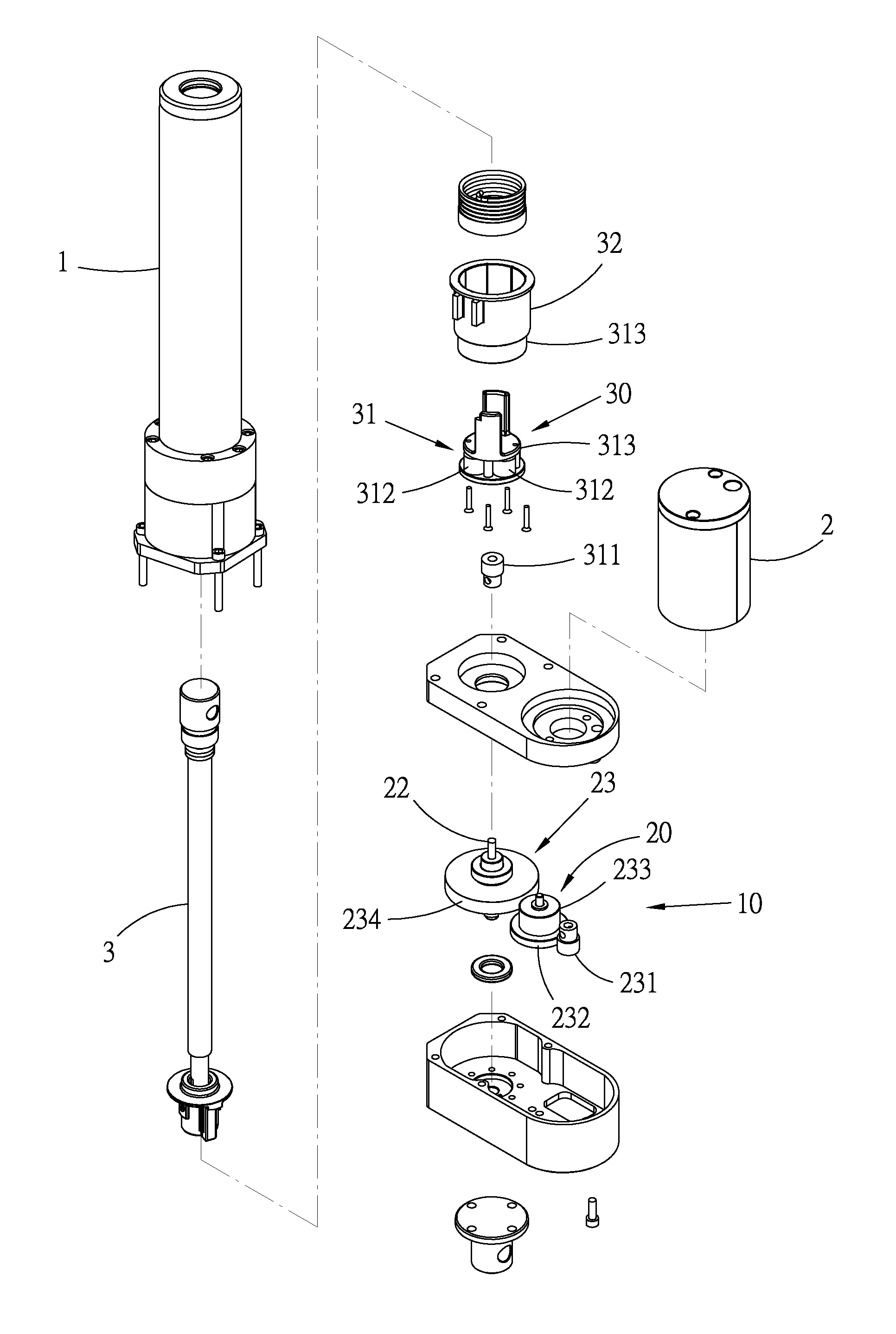
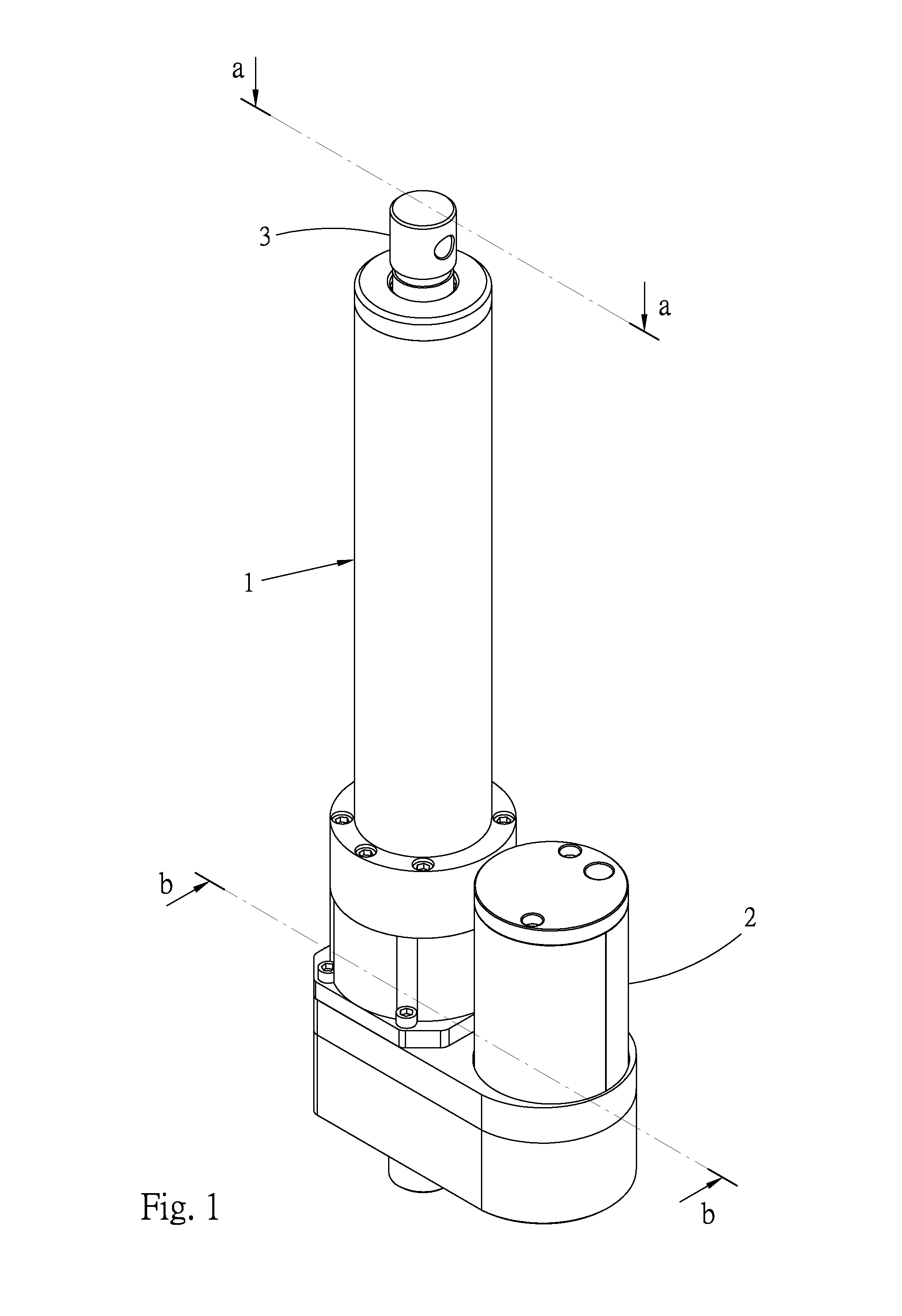
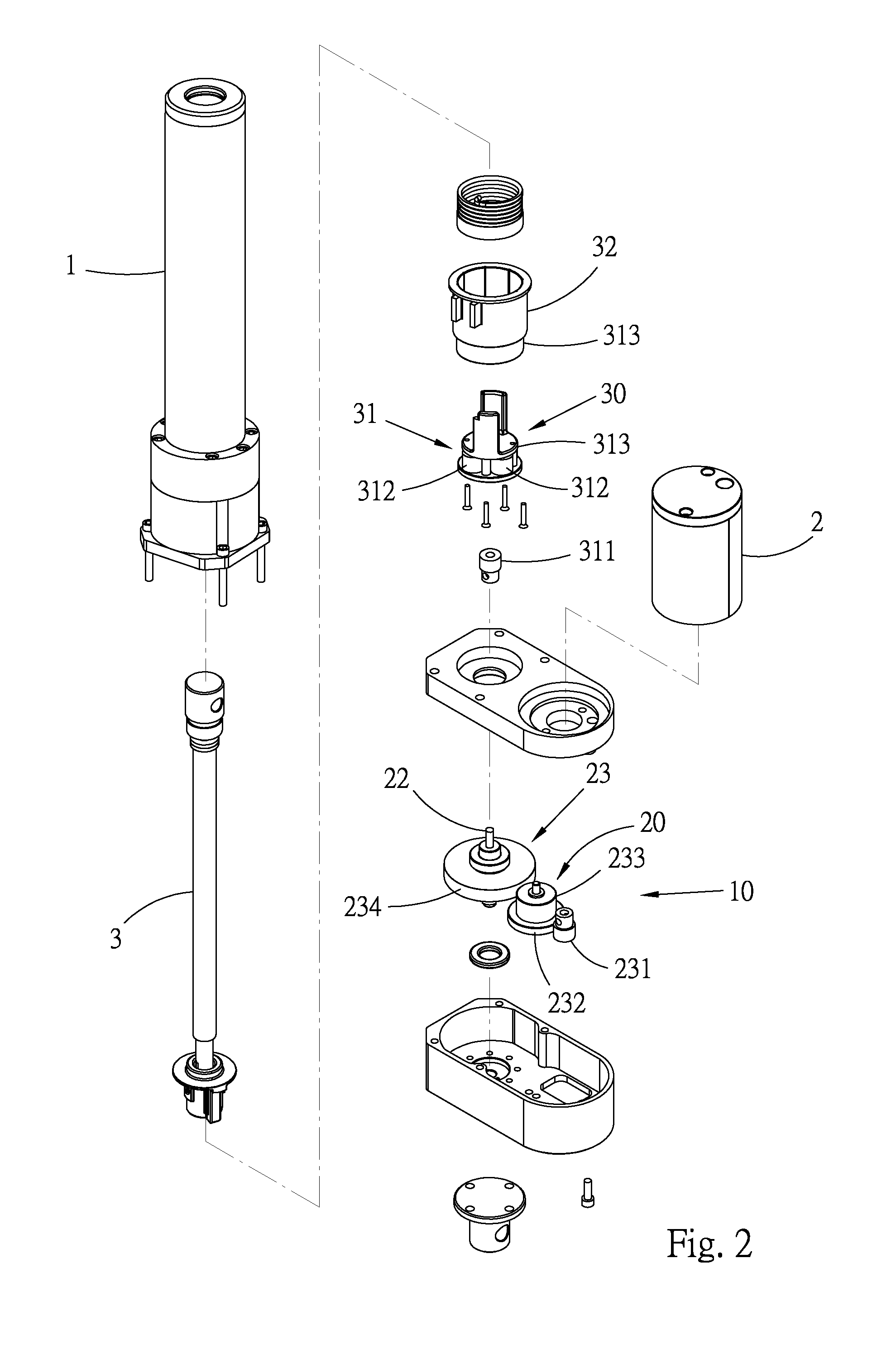
[0016]Please refer to FIGS. 1 to 4. According to a first embodiment, the complex reduction mechanism 10 of linear actuator of the present invention is installed in the linear actuator 1 as a component thereof. The complex reduction mechanism 10 is positioned between a power source 2 and an actuation shaft 3 of the linear actuator 1. The complex reduction mechanism 10 serves to reduce the rotational speed output from the power source 2 and transmits the power of the power source 2 to the actuation shaft 3 for driving the actuation shaft 3 at lower rotational speed and making the actuation shaft 3 linearly axially reciprocally move. To speak more specifically, the complex reduction mechanism 10 includes a primary reducing unit 20 and a secondary reducing unit 30.

[0017]The primary reducing unit 20 includes a primary input shaft 21, a primary output shaft 22 and a primary reducing set 23 positioned between the primary input shaft 21 and the primary output shaft 22. The primary reducing ...


PUM


Abstract

A complex reduction mechanism of linear actuator includes a primary reducing unit and a secondary reducing unit arranged in an axial direction of the primary output shaft. The primary reducing unit includes a primary input shaft, a primary output shaft and a primary reducing set. The primary input shaft is rotationally drivingly coupled with a power output shaft of the power source for transmitting rotational power to the primary reducing set. The primary reducing set reduces the rotational speed and transmits the rotational power to the primary output shaft, which transmits the rotational power outward at lower rotational speed. The secondary reducing unit includes a secondary reducing set and a secondary output section. The secondary reducing set serves to reduce the rotational speed output from the primary output shaft and transmit the rotational power to the secondary output section for driving the actuation shaft to linearly axially reciprocally move.

Description

BACKGROUND OF THE INVENTION[0001]1. Field of the Invention[0002]The present invention relates generally to a linear actuator, and more particularly to a complex reduction mechanism of linear actuator.[0003]2. Description of the Related Art[0004]Conventional linear actuators are widely and reliably used in various fields such as hospital beds, industrial robotic arms and even daily utilities. The existent linear actuator is drivable by an electrical motor via an appropriate transmission mechanism. The rotational power output from the motor is converted into linear power for driving a shaft to axially linearly reciprocally move. Such linear actuator can exert linear force to, for example, lift / lower a hospital bed or drive a robotic arm.[0005]With the advance of various industrial fields, many advanced linear actuators have been developed to satisfy the demands of the industrial fields. The advanced linear actuators can be operated at different speeds to provide different magnitudes o...

Claims


Application Information

Patent Timeline
IPC IPC(8): F16H1/00F16H1/20F16H1/28
CPCF16H25/20F16H2025/2081Y10T74/19647F16H2025/2096F16H2025/2087
Inventor YU, SHENG-YUWEI, CHIA-CHUN
Owner HIWIN MIKROSYST
Why Eureka
Eureka Blog
Learn More