

Drive device
- Summary
- Abstract
- Description
- Claims
- Application Information
AI Technical Summary
Benefits of technology
Problems solved by technology
Method used
Image

Examples
first embodiment
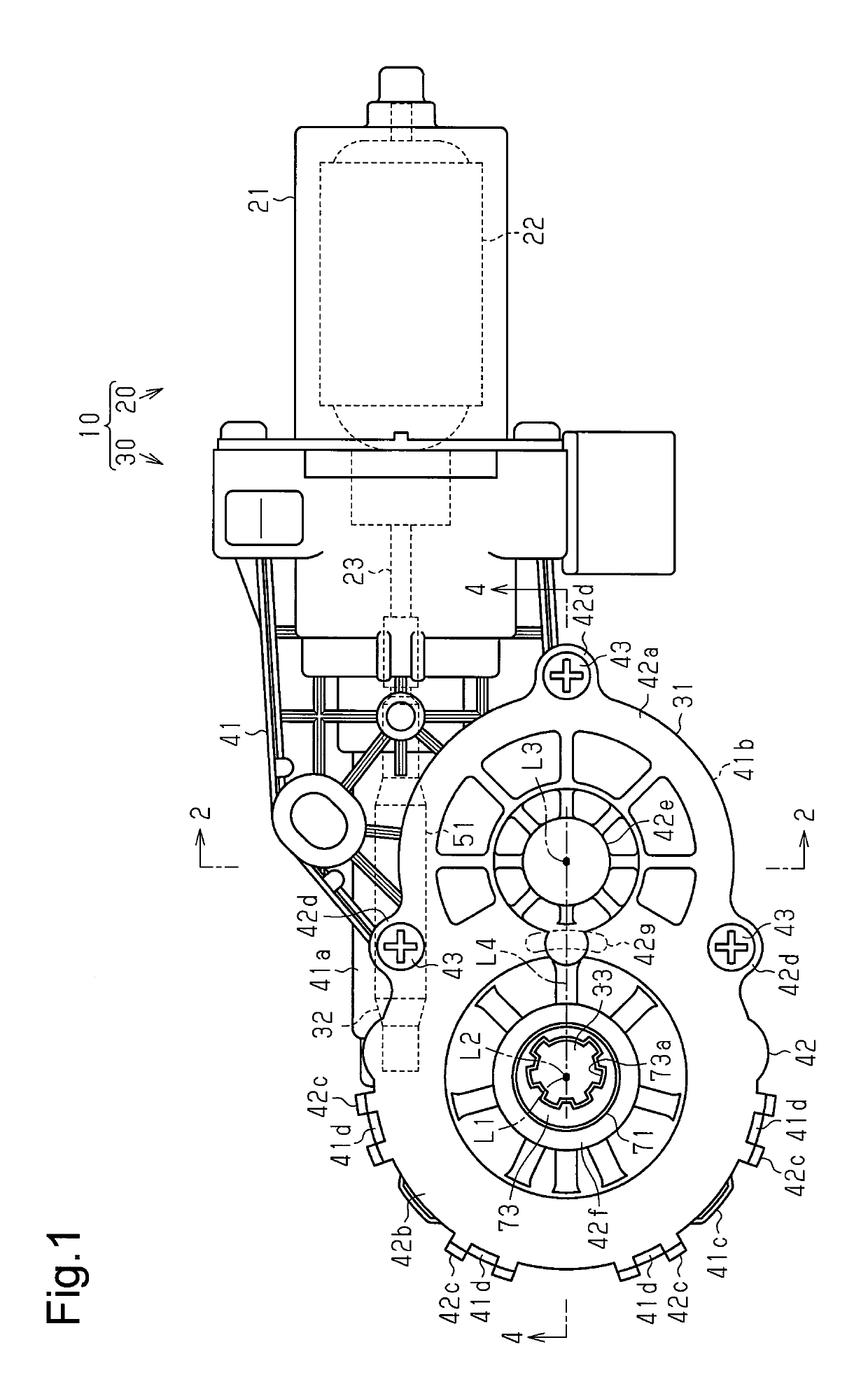
[0016]One embodiment of a drive device will now be described. As shown in FIG. 1, a drive device 10 includes a motor 20 and a reduction unit 30, which is coupled to the motor 20.
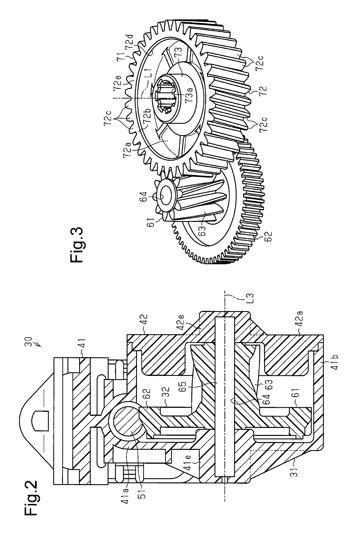
[0017]The motor 20 includes a yoke 21, which is tubular and has a closed end, magnets (not shown), which are fixed to an inner circumference of the yoke 21, and an armature 22, which is accommodated in the yoke 21. The motor 20 drives and rotates the armature 22. The armature 22 includes a rotation shaft 23, which includes a distal end that projects out of an opening of the yoke 21 and into the reduction unit 30. The reduction unit 30 includes an accommodation portion 31, a reduction drive 32, and an output unit 33.
[0018]As shown in FIGS. 1 and 2, the accommodation portion 31 includes a gear housing 41 and a housing cover 42. The gear housing 41 is made of, for example, a resin. The gear housing 41 includes a side end (right end in FIG. 1), which is coupled and fixed to the yoke 21. The side end is open, and...
second embodiment
[0041]One embodiment of a drive device will now be described. In the second embodiment, like or same reference numerals are given to those components that are the same as the corresponding components of the first embodiment.
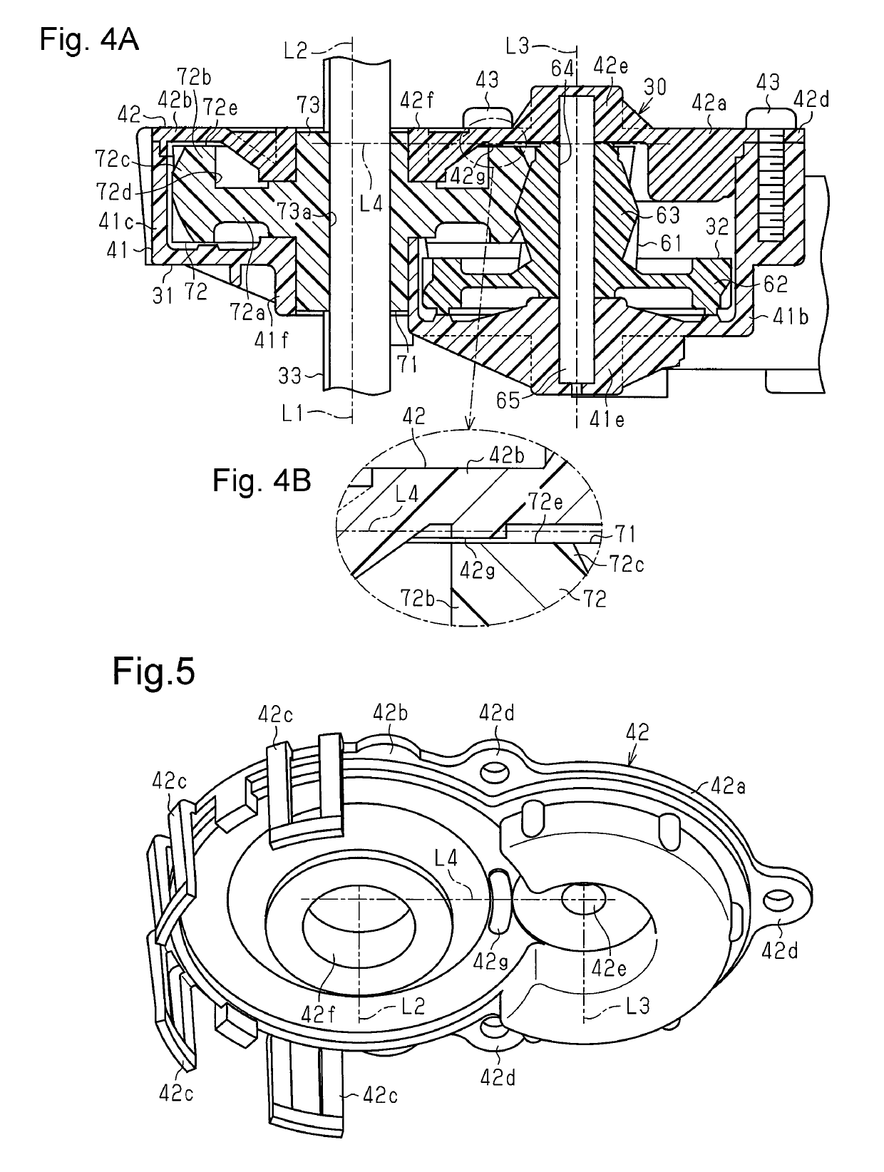
[0042]As shown in FIG. 6A, the base 72b of the large-diameter helical gear 72 includes a tubular inner circumferential surface 72f, which is parallel to the rotation axis L1 of the large-diameter helical gear 72.
[0043]Instead of the restriction portion 42g of the first embodiment, a drive device 80 of the second embodiment includes a restriction portion 42k, which is arranged in the housing cover 42. The restriction portion 42k is formed on the inner surface of the housing cover 42 within a range that includes the straight line L4. That is, the restriction portion 42k is located where at least part of the restriction portion 42k is axially overlapped with the straight line L4. More specifically, the restriction portion 42k is formed within a range that includes a...
PUM
 Abstract
Description
Claims
Application Information