
Ice making assembly and method of operating the same

Inactive Publication Date: 2021-09-09
HAIER US APPLIANCE SOLUTIONS INC
View PDF0 Cites 0 Cited by
  • Summary
  • Abstract
  • Description
  • Claims
  • Application Information

AI Technical Summary

Benefits of technology

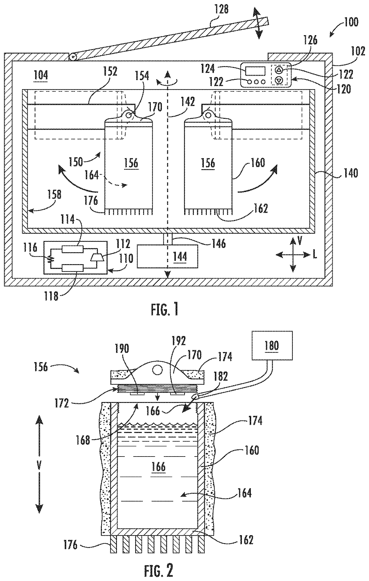
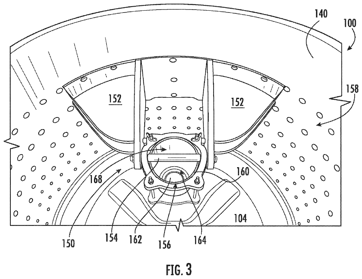
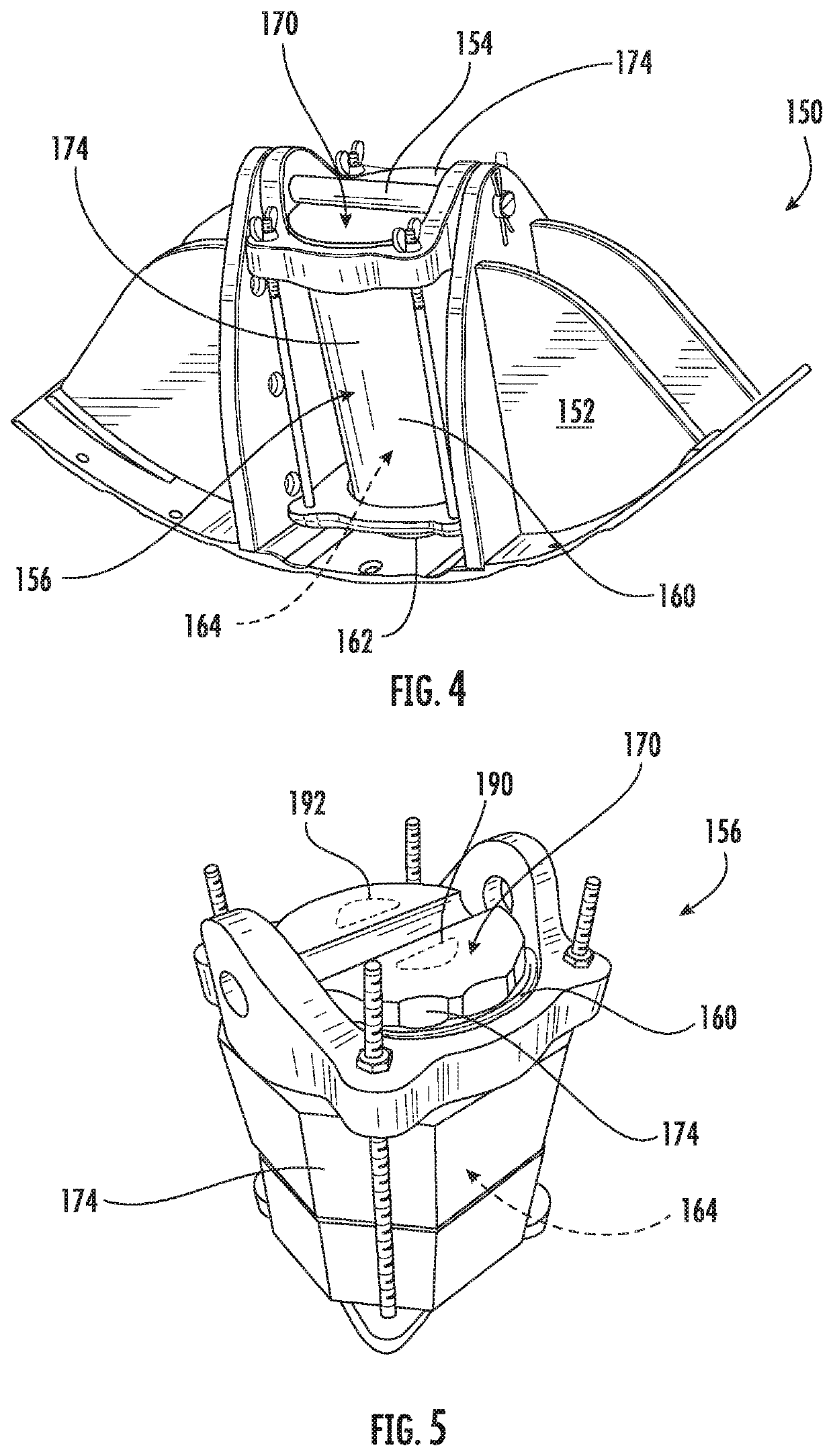
The present invention provides an ice making assembly and a method of operating it that includes a central hub and a mold assembly mechanically coupled to the central hub. The central hub is rotatably mounted within a chilled chamber and the mold assembly defines a mold cavity configured for receiving water. The method includes accelerating the central hub until a rotation speed reaches a target speed and periodically reducing the rotation speed of the central hub to a reduced speed before accelerating back to the target speed. This results in a more efficient ice making process.

Problems solved by technology

However, impurities and gases contained within the water to be frozen may be trapped in a solidified ice cube during the freezing process.
For example, impurities and gases may be trapped near the center or the bottom surface of the ice cube, due to their inability to escape and as a result of the freezing liquid to solid phase change of the ice cube surfaces.
Separate from or in addition to the trapped impurities and gases, a dull or cloudy finish may form on the exterior surfaces of an ice cube (e.g., during rapid freezing of the ice cube).
Although typical ice cubes may be suitable for a number uses, such as temporary cold storage and rapid cooling of liquids in a wide range of sizes, they may present several disadvantages.
As an example, impurities and gases trapped within an ice cube may impart undesirable flavors into a beverage being cooled (i.e., a beverage in which the ice cube is placed) as the ice cube melts.
Such impurities and gases may also cause an ice cube to melt unevenly or faster (e.g., by increasing the exposed surface area of the ice cube).

Method used


Image

  • Ice making assembly and method of operating the same
  • Ice making assembly and method of operating the same
  • Ice making assembly and method of operating the same

Examples


Embodiment Construction

[0018]Reference now will be made in detail to embodiments of the invention, one or more examples of which are illustrated in the drawings. Each example is provided by way of explanation of the invention, not limitation of the invention. In fact, it will be apparent to those skilled in the art that various modifications and variations can be made in the present invention without departing from the scope or spirit of the invention. For instance, features illustrated or described as part of one embodiment can be used with another embodiment to yield a still further embodiment. Thus, it is intended that the present invention covers such modifications and variations as come within the scope of the appended claims and their equivalents.

[0019]As used herein, The terms “includes” and “including” are intended to be inclusive in a manner similar to the term “comprising.” Similarly, the term “or” is generally intended to be inclusive (i.e., “A or B” is intended to mean “A or B or both”). Appro...


PUM


Abstract

An ice making assembly includes a central hub rotatably mounted within a chilled chamber. A mold assembly is attached to the central hub and includes an ice mold that is pivotally coupled to a yoke and defines a mold cavity for receiving water. A drive mechanism rotates the central hub by accelerating the central hub until the rotation speed reaches a target speed and periodically reducing the rotation speed of the central hub to a reduced speed before accelerating back to the target speed until an ice billet is formed.

Description

FIELD OF THE INVENTION[0001]The present subject matter relates generally to ice making assemblies, and more particularly to ice making assemblies that use centrifugal force to create clear billets of ice.BACKGROUND OF THE INVENTION[0002]In domestic and commercial applications, ice is often formed as solid cubes, such as crescent cubes or generally rectangular blocks. Specifically, certain ice makers include a freezing mold that defines a plurality of cavities that can be filled with liquid water, and such liquid water can freeze within the plurality of cavities to form solid ice cubes. Typical solid cubes or blocks may be relatively small in order to accommodate a large number of uses, such as temporary cold storage and rapid cooling of liquids in a wide range of sizes.[0003]In typical ice making appliances, water in the cavities begins to freeze and solidify first from its sides and outer surfaces (including a top water surface that may be directly exposed to freezing air), and the...

Claims


Application Information

Patent Timeline
IPC IPC(8): F25C1/10F25C5/08
CPCF25C1/10F25C5/08F25C2600/04F25C2400/02F25C2301/00F25C1/20
Inventor FROELICHER, STEPHEN BERNARDALLGEIER, BRIAN
Owner HAIER US APPLIANCE SOLUTIONS INC
Learn More