Crane, and crane control method

Active Publication Date: 2018-03-29
MITSUI E&S MACHINERY CO LTD
View PDF1 Cites 0 Cited by
  • Summary
  • Abstract
  • Description
  • Claims
  • Application Information

AI Technical Summary

Benefits of technology

[0018]In the present invention, the rotation speed in the command to the motor is reduced such that the greater the torque of the motor measured by the torque measurement unit is, the greater the ratio of the reduction is. Accordingly, the torques generated in the motors are controlled to be even. Making the torques generated in the motors even can reduce misalignment in the travel direction between the travel devices arranged on the opposite sides. Accordingly, strain is less likely to be generated in the crane structure and the present invention is advantageous in suppressing vibration occurring in the crane structure due to this strain.
[0019]The crane can be configured to include a brake device configured to apply a brake to the travel devices after a predetermined waiting time elapses from a point where a speed command of maintaining

Problems solved by technology

Although the damping masses can reduce the swinging of the boom which occurs in travel and stop of

Method used


Image

  • Crane, and crane control method
  • Crane, and crane control method
  • Crane, and crane control method

Examples


Embodiment Construction

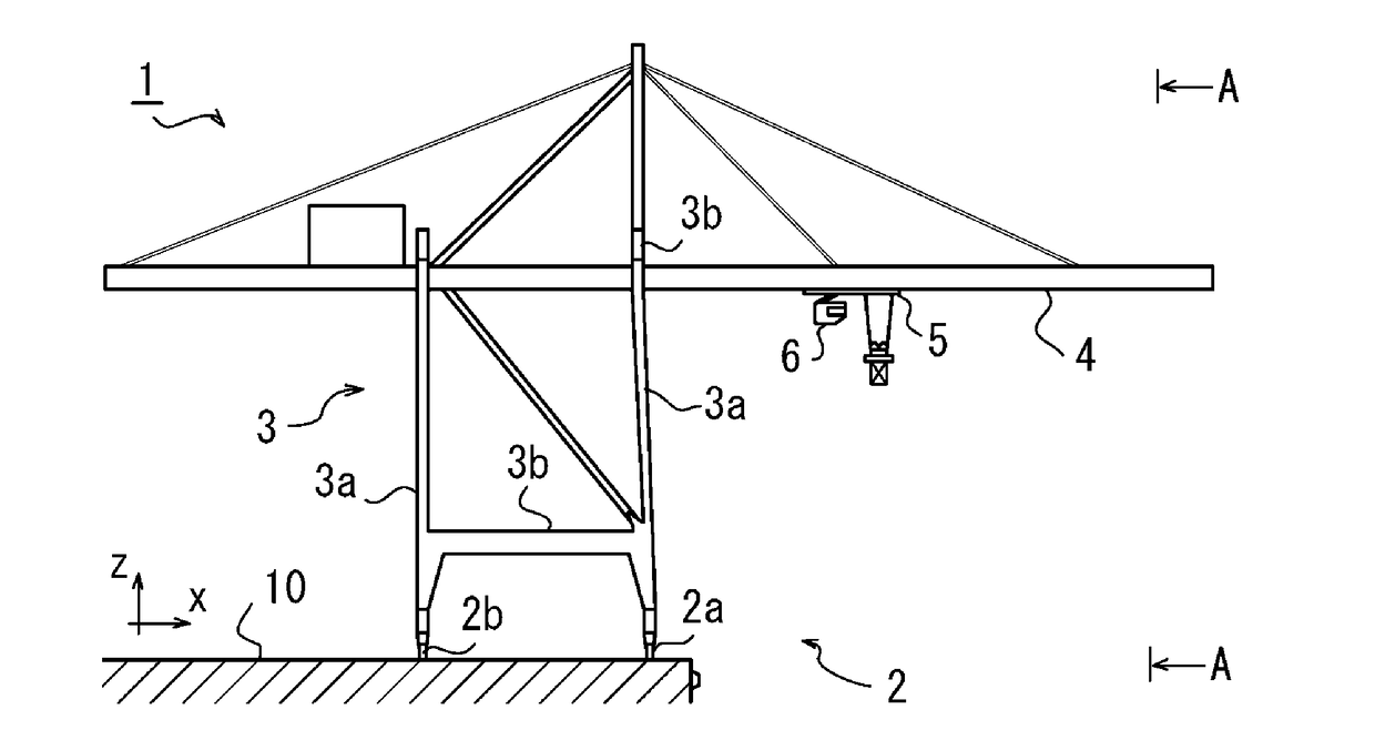
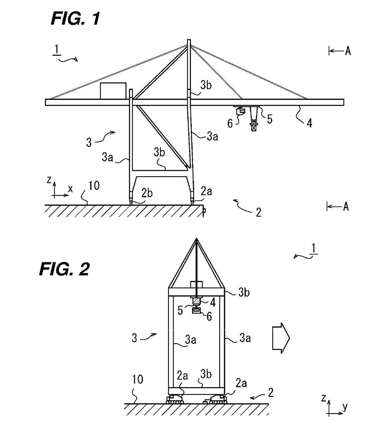
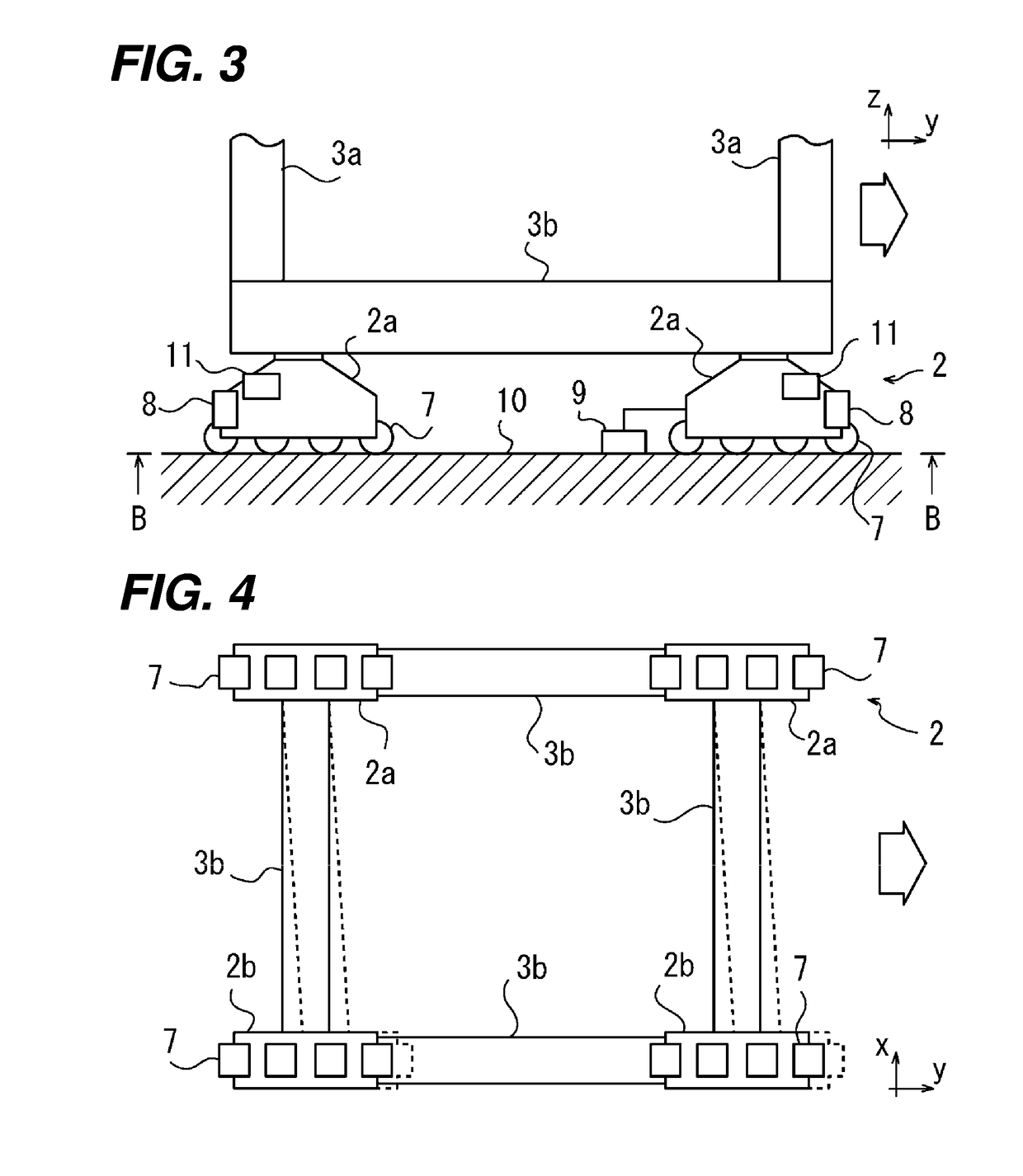
[0030]A crane and a crane control method of the present invention are described below based on the embodiments illustrated in the drawings. Note that, in the drawings, a travel direction of the crane and travel devices is illustrated by an arrow y, a transverse direction which is a horizontal direction orthogonal to the travel direction y is illustrated an arrow x, and an up-down direction is illustrated by an arrow Z.

[0031]As illustrated in FIGS. 1 to 4, a crane 1 of the present invention is configured to be, for example, a quay crane. The quay crane 1 includes travel devices 2 each two of which are arranged on the opposite sides with a gap in the transverse direction x being the horizontal direction orthogonal to the travel direction y of the crane 1, a crane structure 3 which is supported by the travel devices 2, and a boom 4 which is supported by the crane structure 3 and which extends in the transverse direction x.

[0032]The crane structure 3 includes four leg members 3a extendi...


PUM


Abstract

Provided is a crane which can suppress deformation and vibration of a crane structure in travel and stop of the crane. Inverters are installed respectively in travel devices which are arranged on the opposite sides with a gap in a transverse direction. Each of the inverters independently measures a torque generated in a motors to which the inverter is connected and reduces the rotation speed in the command from a controller to the motor such that the greater the measured torque is, the greater a ratio of reduction is.

Description

TECHNICAL FIELD[0001]The invention of the present application relates to a crane including travel devices which are arranged on the opposite sides with a gap in a transverse direction and a crane structure which is supported by the travel devices, more specifically to a crane which can suppress deformation and vibration of the crane structure when the crane travels and stops.BACKGROUND ART[0002]A quay crane is used as a loading-unloading machine for loading and unloading containers and the like in places such as ports. The quay crane includes travel devices which are arranged on the opposite sides with a gap in a transverse direction (also referred to as sea-land direction) being a horizontal direction orthogonal to a travel direction along the quay, a crane structure which is supported by the travel devices, and a boom which is supported by the crane structure and which extends in the transverse direction. The travel devices include a sea-side travel device arranged on the sea side...

Claims


Application Information

Patent Timeline
IPC IPC(8): B66C13/22B66C9/18B66C9/10
CPCB66C13/22B66C9/18B66C9/10B66C9/12
Inventor ISHII, KATSUNORIOHI, KOJIKUBO, HIROSHI
Owner MITSUI E&S MACHINERY CO LTD
Why Eureka
Try Eureka