Lens device

a technology of lens and lens barrel, which is applied in the direction of mountings, instruments, camera body details, etc., can solve the problems of deterioration of optical properties, expansion and shrinkage of plastic lenses and lens bars, and inability to suppress the misalignment between lenses and lens bars and between lenses insufficiently, so as to achieve the effect of suppressing the misalignment of optical axes

Active Publication Date: 2006-07-20
MAXELL HLDG LTD
View PDF3 Cites 37 Cited by
  • Summary
  • Abstract
  • Description
  • Claims
  • Application Information

AI Technical Summary

Benefits of technology

[0009] It is an object of the present invention to solve the above problems and provide a lens device capable of sufficiently sup...

Problems solved by technology

The plastic lens and lens-barrel, however, are subject to expansion and shrinkage due to temperature or humidity change.
Thus, even if core alignment is performed when inserting and fixing the lens into the lens-barrel to assemble them, the misalignment of the optical axes b...

Method used


Image

  • Lens device
  • Lens device
  • Lens device

Examples


Embodiment Construction

[0052] From the invention thus described, it will be obvious that the embodiments of the invention may be varied in many ways. Such variations are not to be regarded as a departure from the spirit and scope of the invention, and all such modifications as would be obvious to one skilled in the art are intended for inclusion within the scope of the following claims.

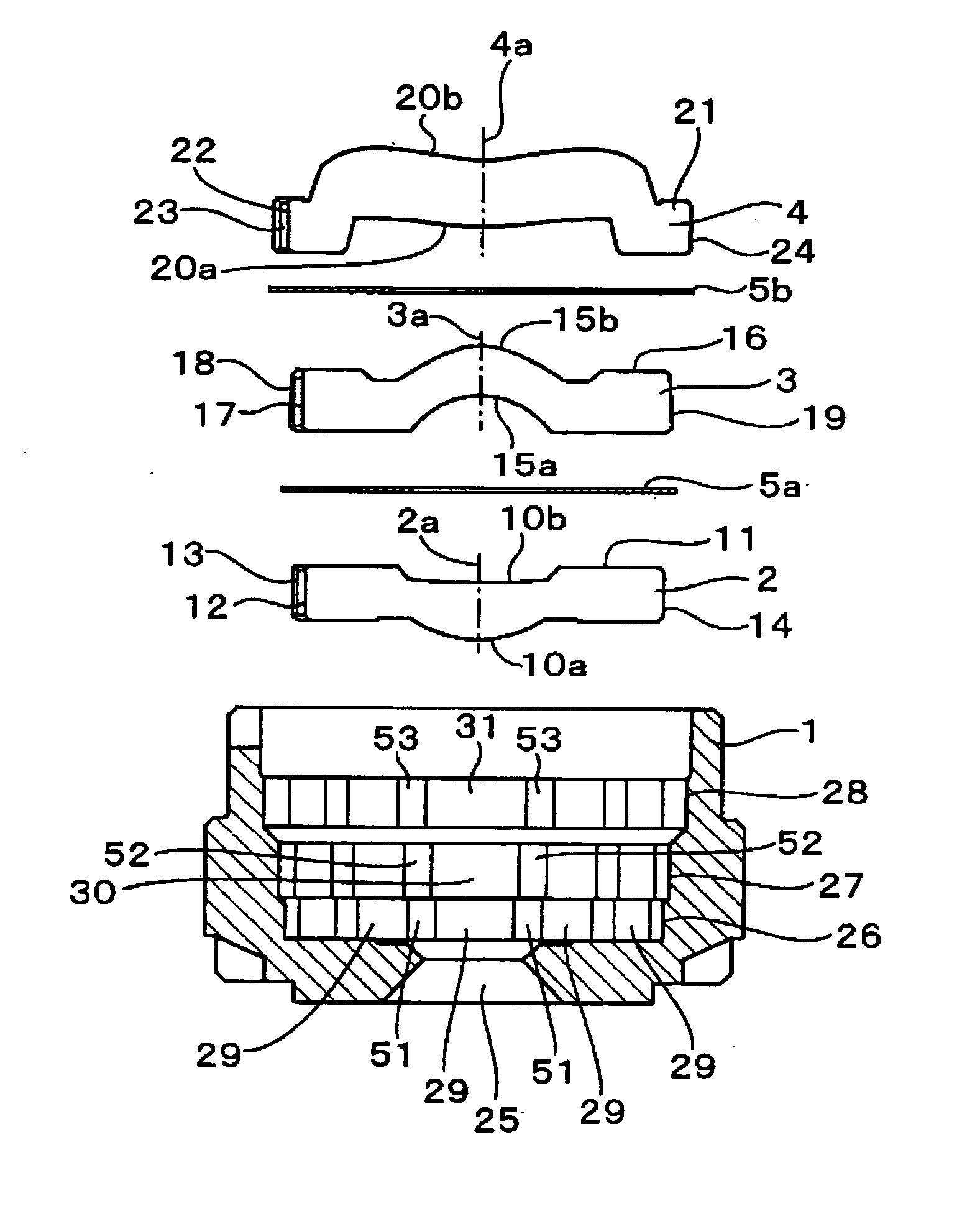
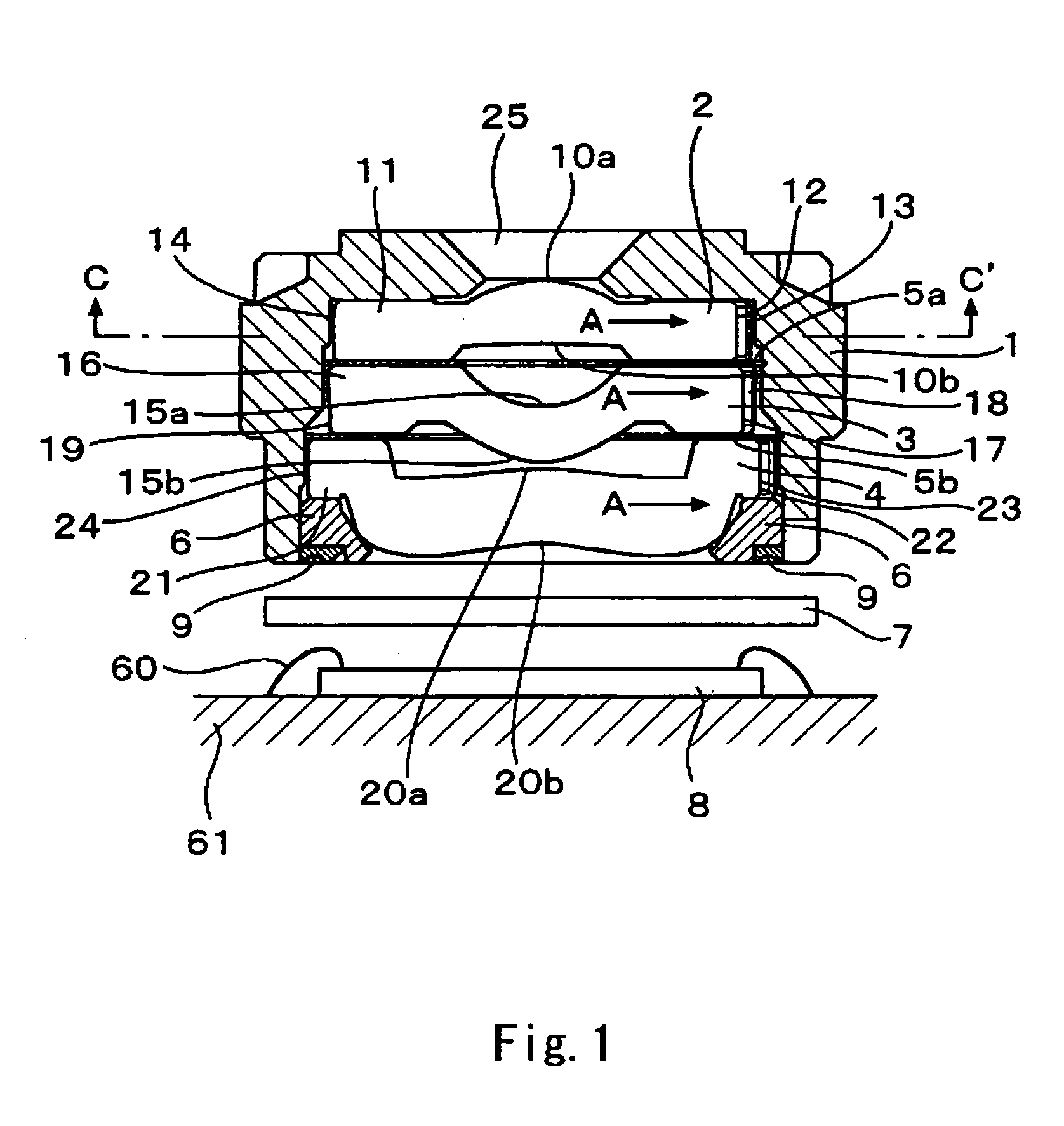
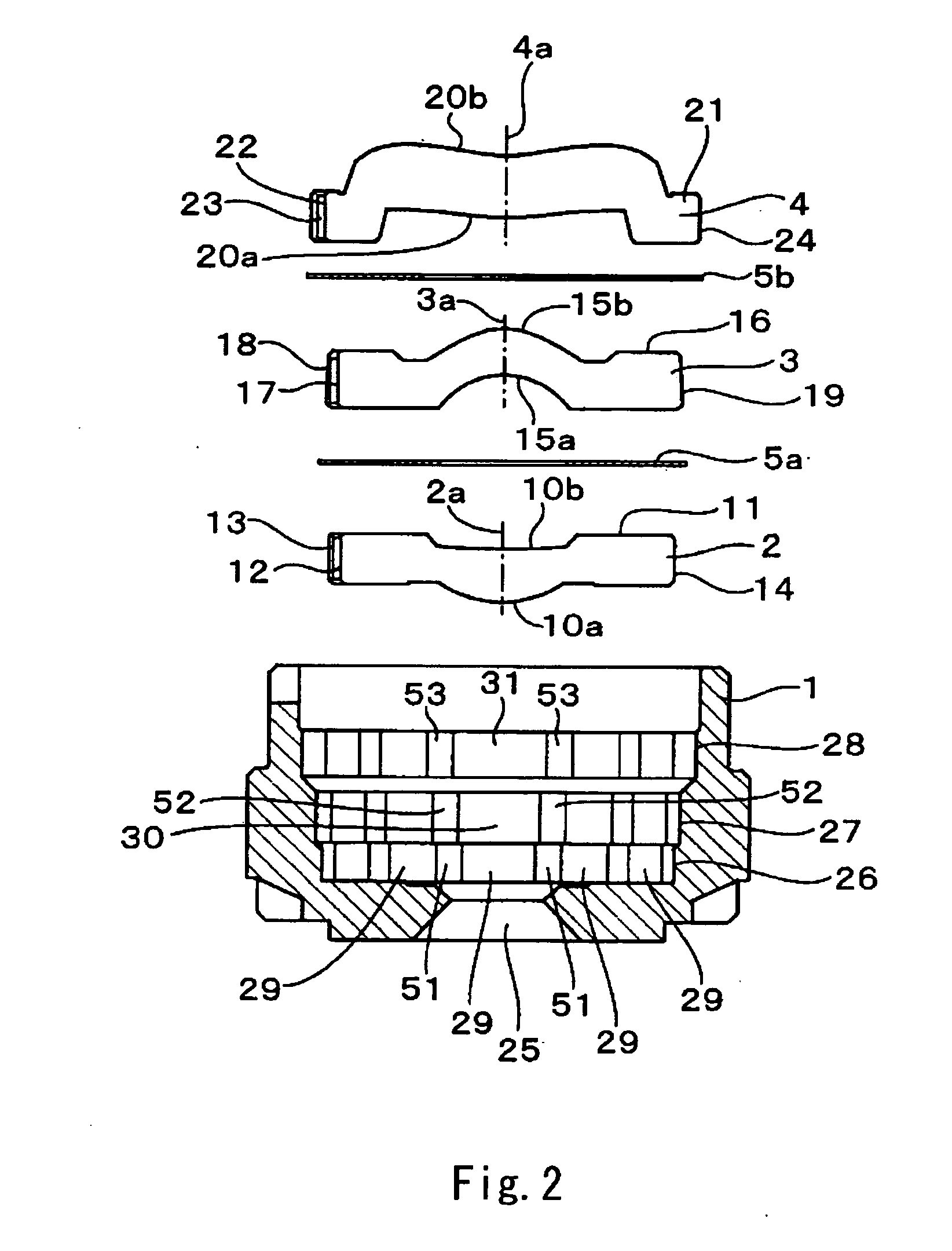
[0053] An embodiment of the lens device according to the present invention is described hereinafter with reference to the drawings. FIG. 1 is a cross-sectional view of a lens device according to a first embodiment of the invention. FIG. 2 is an exploded cross-sectional view of the main part of the lens device.

[0054] As shown in FIGS. 1 and 2, the lens device of this embodiment is basically composed of a lens-barrel 1, a first positive lens 2, a second positive lens 3, a correction lens 4, a diaphragm 5 and a lens holder 6. The black lens-barrel 1 is made of composite of polycarbonate resin, glass fiber, and black pigment ...


PUM


Abstract

In a lens device, plastic lenses having circular outer periphery are placed in a plastic lens-barrel having an octagonal or more complex polygonal inner surface in such a way that the outer peripheral surfaces of the lenses are press contacted to the inner surface of the polygonal shape. This lens device has press contact portions that are pressed by the lens outer peripheral surface and the lens-barrel inner surface in the vicinity and in both sides of gate traces where optical axis displacement is large so as to suppress the displacement of the gate trace by the press contact portions.

Description

BACKGROUND OF THE INVENTION [0001] 1. Field of the Invention [0002] The present invention relates to a lens device where a lens used for a camera or the like is inserted and fixed in a lens-barrel. [0003] 2. Description of Related Art [0004] A digital camera, a mobile phone camera and so on use a lens device in which one or a plurality of lenses are inserted and fixed in a lens-barrel. Such a lens device is manufactured by performing core alignment so as to align the optical axes of a lens and a lens-barrel and the optical axes of a plurality of lenses and then inserting and fixing the lenses into the lens-barrel. [0005] In such a lens device, a plastic lens, a plastic lens-barrel and so on are used because they are low cost and easy to form a desired shape. [0006] The plastic lens and lens-barrel, however, are subject to expansion and shrinkage due to temperature or humidity change. Thus, even if core alignment is performed when inserting and fixing the lens into the lens-barrel to...

Claims


Application Information

Patent Timeline
IPC IPC(8): G02B7/02
CPCG02B7/021G02B7/022G02B13/0035G02B27/62
Inventor HIRATA, HIROYUKIHASHIMOTO, MASATOSHI
Owner MAXELL HLDG LTD
Why Eureka
Try Eureka