Cable connection structure and cable connection method

Inactive Publication Date: 2011-12-15
HITACHI METALS LTD
View PDF13 Cites 15 Cited by
  • Summary
  • Abstract
  • Description
  • Claims
  • Application Information

AI Technical Summary

Benefits of technology

[0028]According to one embodiment of the invention, a cable connection structure or cable connection method is constructed or conducted such that (I) a one component moisture-curing elastic adhesive as a positioning member is applied between a signal electrode and a ground electrode on a board using a dispenser, (II) all inner insulators of a multi-core cable are pressed together by a pressure tool to be attached to the one component moisture-curing elastic adhesive, (III) an adjusting needle having a tip diameter smaller than a predetermined arrangement pitch distance between

Problems solved by technology

However, the cable positioning jig disclosed in patent document 1 has a problem that it is difficult to form cable positioning grooves which correspond to an extremely narrower pitch.
Therefore, there is a problem that a cable is curved when plural cable conductors are fitted to the cable positioning grooves on the cable positioning jig of patent document 1 and are then pressed and fixed, resulting in that the cable conductors are not precisely placed in the cable positioning grooves.
On the other hand, the method of conn

Method used


Image

  • Cable connection structure and cable connection method
  • Cable connection structure and cable connection method
  • Cable connection structure and cable connection method

Examples


first embodiment

[0038]Structure of multi-core cable

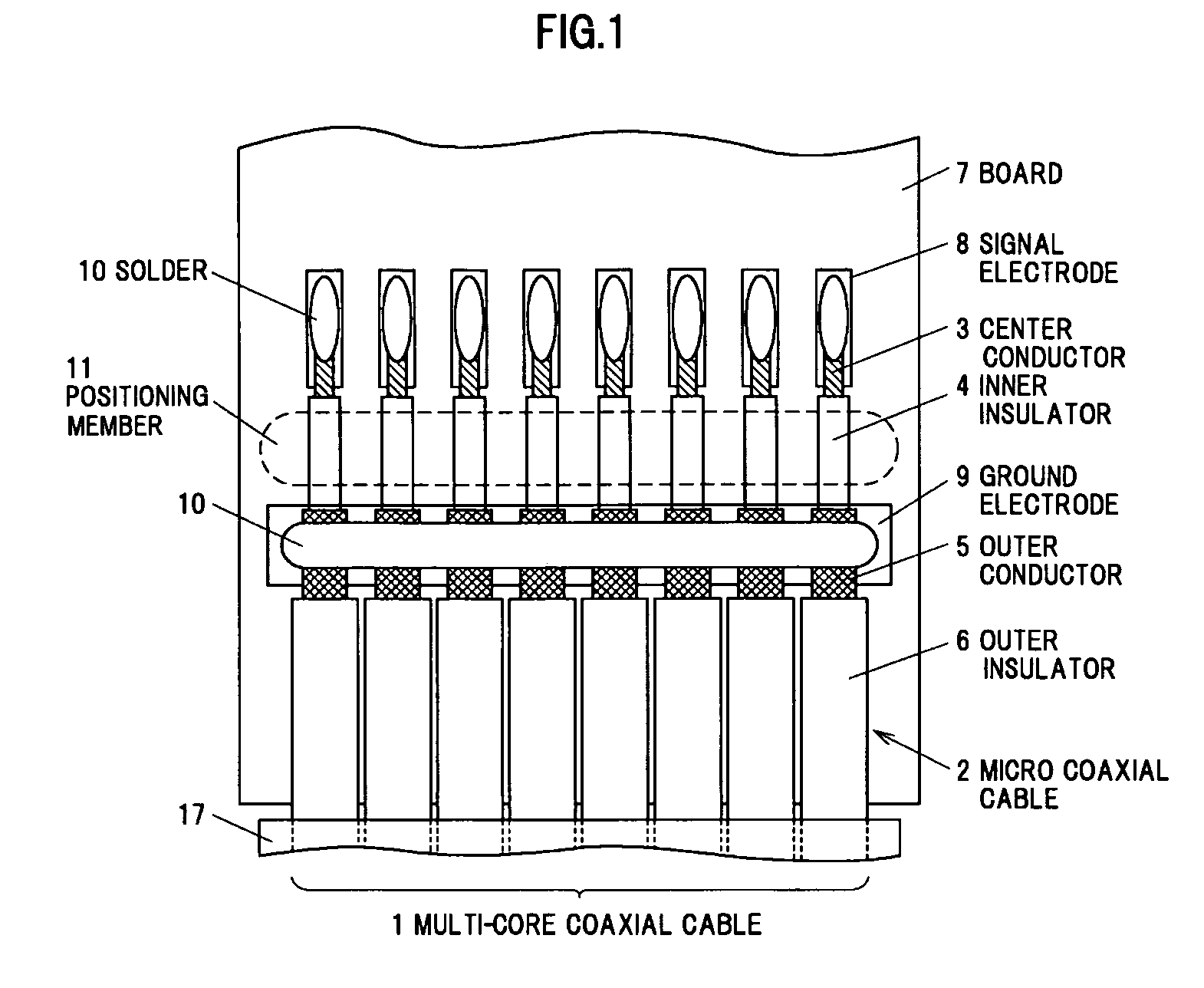
[0039]The reference numeral 1 in FIG. 1 shows the entirety of a multi-core cable which is arranged on a print circuit board 7 (hereinafter referred to as “board 7”). The multi-core cable 1 in the illustrated example is formed by aligning eight micro coaxial cables 2 in parallel at an arrangement pitch distance of 0.15 mm and then integrally coating with an insulation laminated tape 17.

[0040]As shown in FIG. 1, each of the eight micro coaxial cables 2 which compose the multi-core cable 1 is integrally formed with a center conductor 3 with an outer diameter of 0.03 mm formed by twisting seven core wires each having a diameter of 0.01 mm, an inner insulator 4 with an outer diameter of 0.06 mm which covers the outer periphery of the center conductor 3, an outer conductor 5 with an outer diameter of 0.1 mm which is a served shield formed of a core wire with an outer diameter of 0.016 mm to cover the outer periphery of the inner insulator 4, and an outer...

second embodiment

[0064]A specific embodiment of a cable connection method for obtaining the cable connection structure in the first embodiment will be described in detail below in reference to FIGS. 2 to 6. It should be noted that a typical example of the first embodiment is given in the second embodiment and it is obvious that the invention is not limited to the illustrated example.

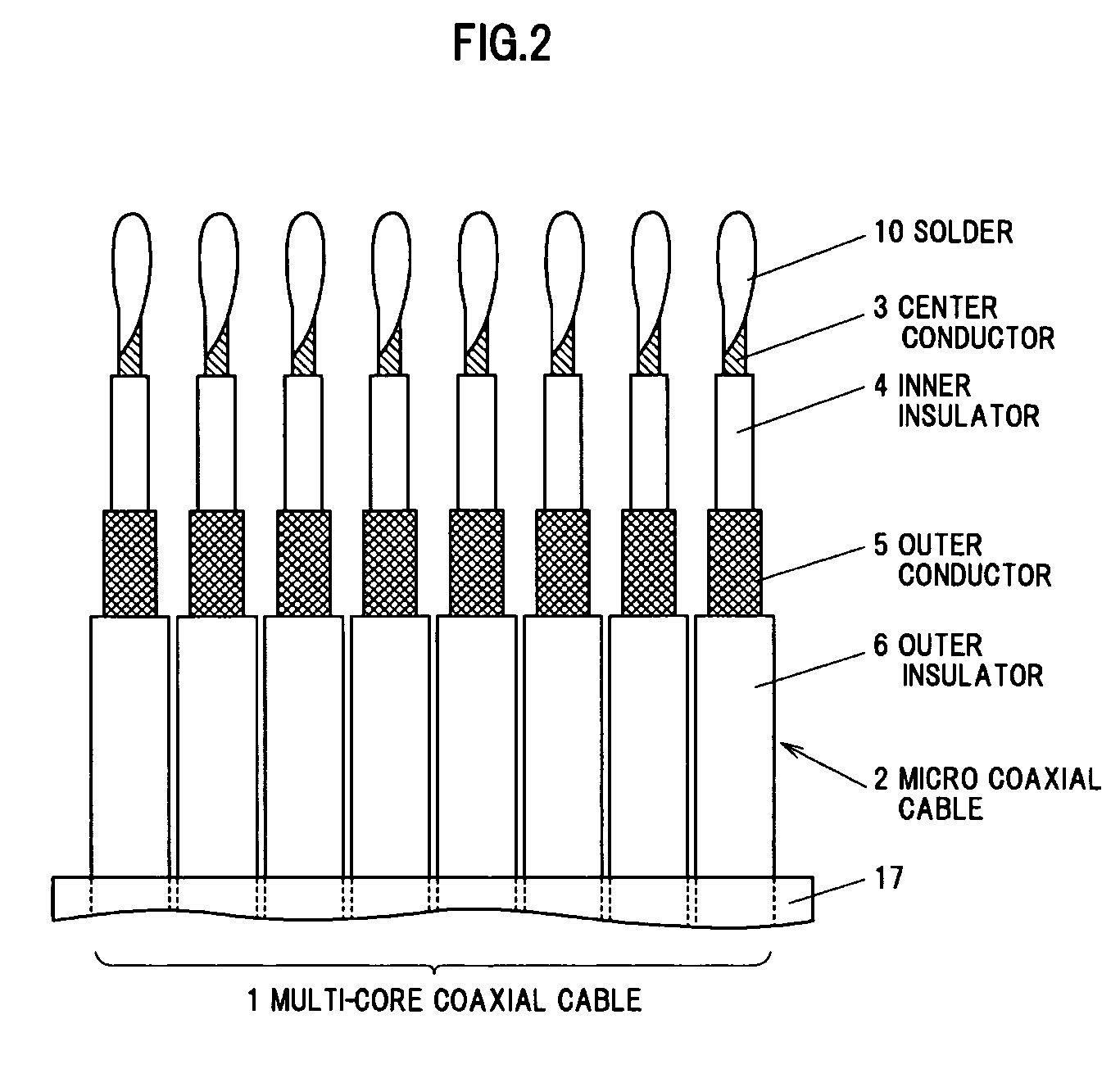
[0065]Terminal treatment of multi-core cable

[0066]Before the eight micro coaxial cables 2 integrated by the laminated tape 17 is electrically connected to the signal electrode 8 and the ground electrode 9 of the board 7, the terminal treatment of the multi-core cable 1 using a CO2 laser or a YAG laser is each performed in the terminal treatment processes, which are a jacket cutting process, an outer conductor cutting process and an inner insulator cutting process. In a preferred form, the end portion of the multi-core cable 1 which is shown in FIG. 2 is effectively obtained through the terminal treatment processes shown ...

third embodiment

[0093]As obvious from the above explanation, the cable connection structure and the cable connection method of the invention have been described based on each of the embodiments, however, the invention is not limited to each of the embodiments, the modification and the illustrated examples, and can be implemented in various modes without departing from the gist thereof. Another embodiment, e.g., shown below, is applicable in the invention.

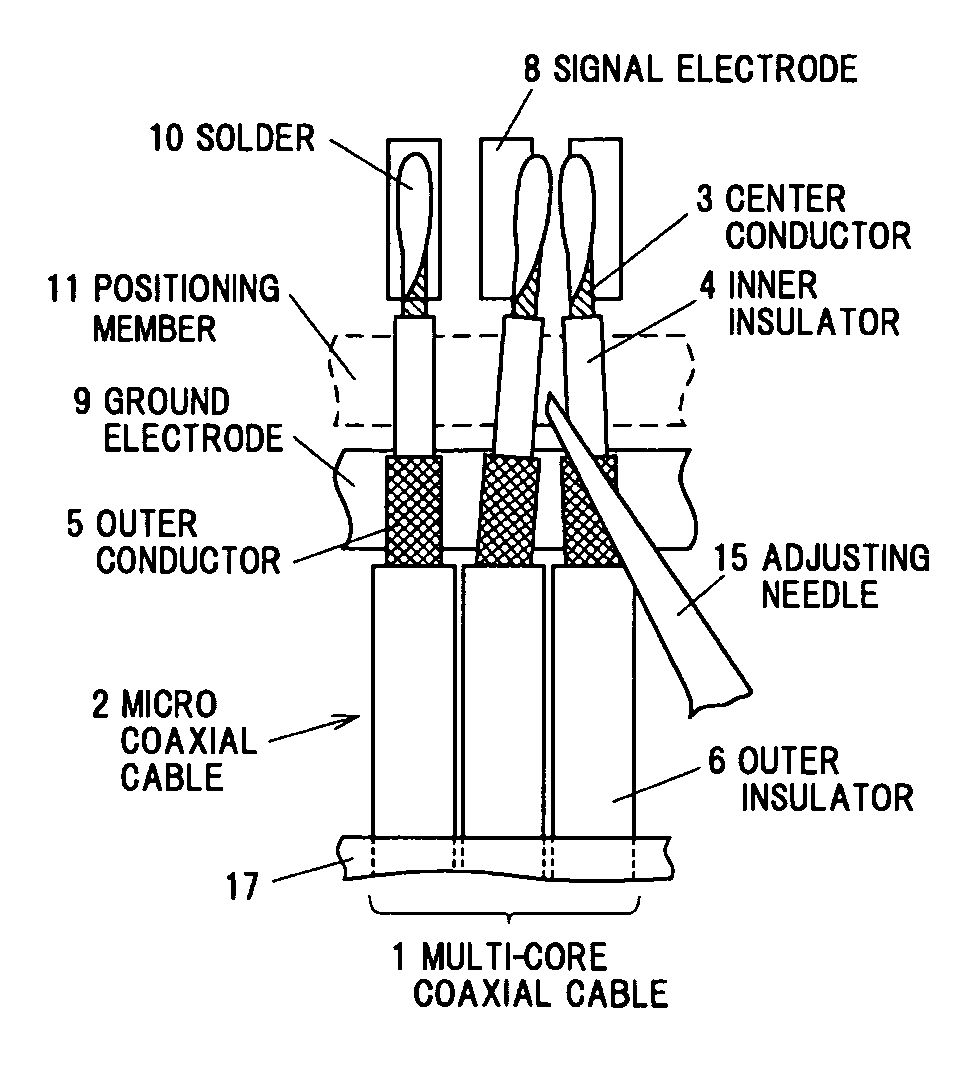
[0094]The first and second embodiments are configured such that the position of the center conductor 3 of the multi-core cable 1 is adjusted without using a positioning jig, however, the position of the center conductor 3 is adjusted using a positioning jig in the third embodiment. Note that, members substantially the same as those in each of the embodiments are denoted by the same names and reference numerals. Therefore, the detailed description for the members substantially the same as those in each of the embodiments will be omitted.

[0095]FIGS. ...


PUM

PropertyMeasurementUnit
Energyaaaaaaaaaa
Adhesivityaaaaaaaaaa
Tackinessaaaaaaaaaa

Abstract

A cable connection structure includes a multi-core coaxial cable connected to a board. The multi-core coaxial cable includes a plurality of parallel-arranged coaxial cables each including a center conductor and an inner insulator, an outer conductor and an outer insulator sequentially formed on an outer periphery of the center conductor. The board includes a signal electrode connected to the center conductor and a ground electrode connected to the outer conductor. The cable connection structure further includes a positioning member lying between the signal electrode and the ground electrode for positioning the center conductor while the inner insulator is attached to the positioning member.

Description

[0001]The present application is based on Japanese Patent Application No. 2010-133118 filed on Jun. 10, 2010, the entire contents of which are incorporated herein by reference.BACKGROUND OF THE INVENTION[0002]1. Field of the Invention[0003]This invention relates to a cable connection structure and a cable connection method for connecting a center conductor of a cable to an electrode formed on a printed circuit board etc.[0004]2. Description of the Related Art[0005]In recent years, reduction in size and weight of various terminal devices, such as, e.g., notebook computer or cellular phone, is demanded in the field of electrical and electronic equipment. Those terminal devices have a structure in which, e.g., an upper housing provided with a liquid crystal display is coupled and fixed to a lower housing provided with a controller via a hinge portion which is three-dimensionally movable, and operability and functionality thereof have been enhanced.[0006]Such terminal devices need to tr...

Claims


Application Information

Patent Timeline
IPC IPC(8): H01R9/05H01B13/20
CPCH01R4/027Y10T29/49123H01R9/0515
Inventor TANAKA, KOTAROYAGUCHI, AKIHIROOYAMA, HIROSHI
Owner HITACHI METALS LTD
Why Eureka
Try Eureka