Wireless power supply apparatus

a power supply apparatus and wireless technology, applied in the direction of wireless communication, inductance, secret communication, etc., can solve the problem of small power use efficiency of the apparatus

Active Publication Date: 2011-09-29
ADVANTEST CORP
View PDF23 Cites 37 Cited by
  • Summary
  • Abstract
  • Description
  • Claims
  • Application Information

AI Technical Summary

Problems solved by technology

However, the power use efficiency thereof is small.

Method used


Image

  • Wireless power supply apparatus
  • Wireless power supply apparatus
  • Wireless power supply apparatus

Examples


Embodiment Construction

[0031]The invention will now be described based on preferred embodiments which do not intend to limit the scope of the present invention but exemplify the invention. All of the features and the combinations thereof described in the embodiment are not necessarily essential to the invention.

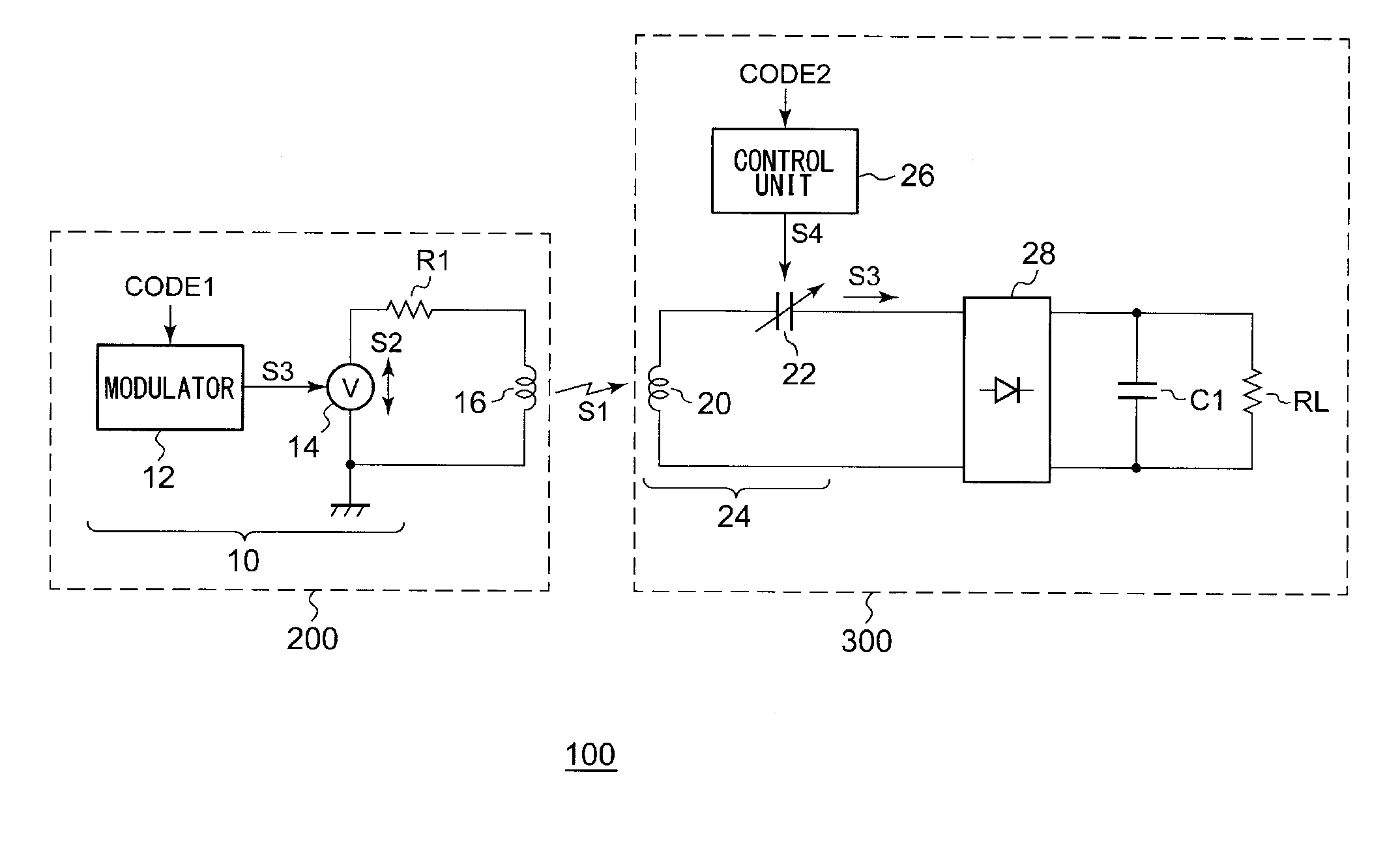
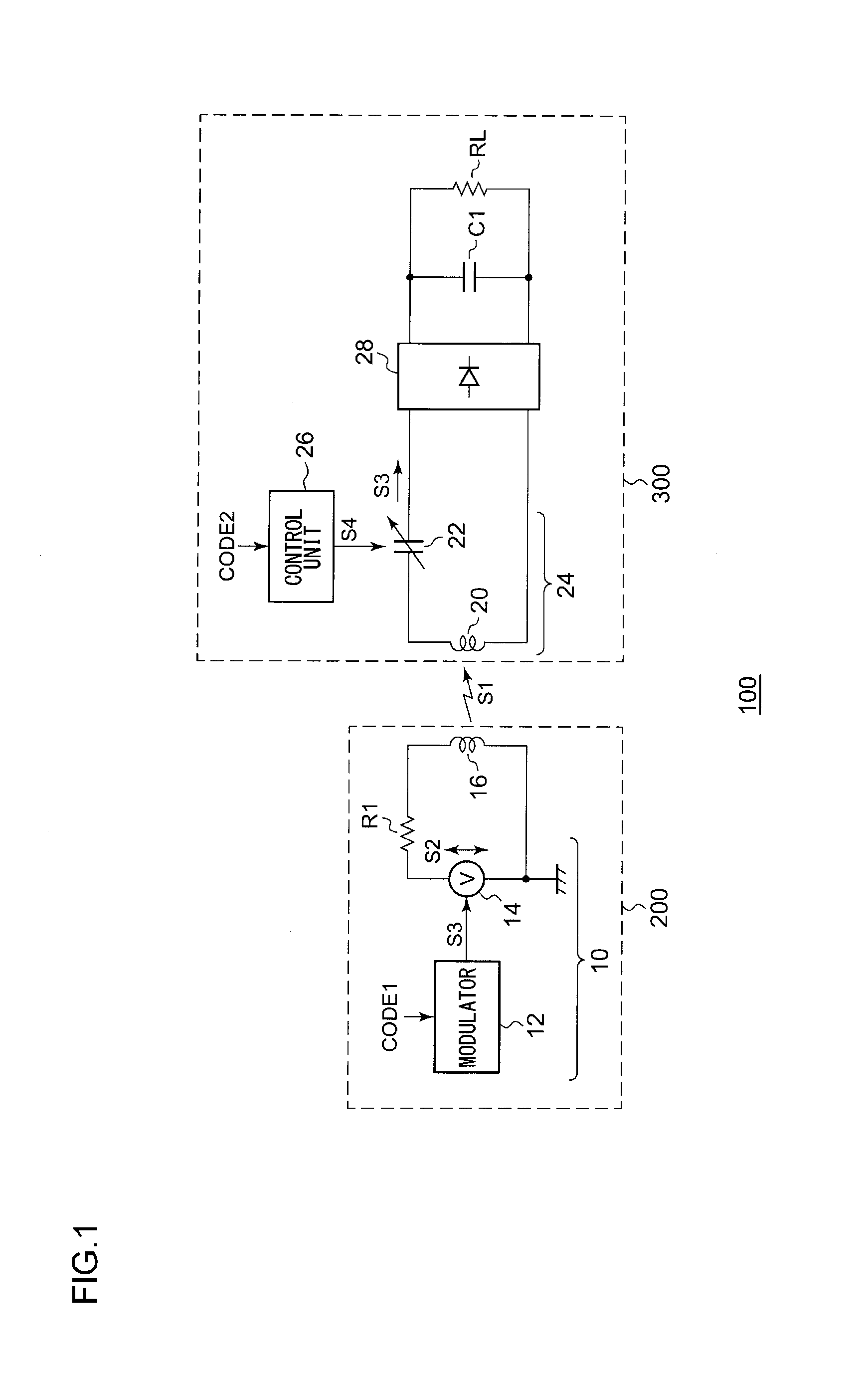
[0032]FIG. 1 is a block diagram which shows a configuration of a wireless power supply system 100 according to an embodiment. The wireless power supply system 100 includes a wireless power supply apparatus 200 and a wireless power reception apparatus 300. First, description will be made regarding the wireless power supply apparatus 200.

[0033]The wireless power supply apparatus 200 transmits an electric power signal to the wireless power reception apparatus 300. As an electric power signal S1, the wireless power supply system 100 uses the near-field component (electric field, magnetic field, or electromagnetic field) of electromagnetic waves that has not become radio waves.

[0034]The wireless power s...


PUM

PropertyMeasurementUnit
power use efficiencyaaaaaaaaaa
frequencyaaaaaaaaaa
frequencyaaaaaaaaaa

Abstract

A wireless power supply apparatus generates an electric signal frequency-modulated or otherwise phase-modulated according to a transmission-side code that is determined beforehand with a wireless power reception apparatus. The electric signal thus generated is transmitted via a transmission coil so as to generate an electric power signal including any one of an electric field, a magnetic field, and an electromagnetic field. The wireless power reception apparatus receives the electric power signal using a reception coil. A control unit changes the impedance of a resonance circuit that comprises the reception coil and a resonance capacitor, according to a reception-side code that is to correspond to the transmission-side code.

Description

BACKGROUND OF THE INVENTION[0001]1. Field of the Invention[0002]The present invention relates to a wireless power supply technique.[0003]2. Description of the Related Art[0004]In recent years, wireless (contactless) power transmission has been receiving attention as a power supply technique for electronic devices such as cellular phone terminals, laptop computers, etc., or for electronic vehicles. Wireless power supply transmission can be classified into three principal methods using an electromagnetic induction, an electromagnetic wave, and an electric field / magnetic field resonance.[0005]The electromagnetic induction method is employed to supply electric power at a short range (several mm or less), which enables electric power of several hundred watts to be transmitted in a band that is equal to or lower than several hundred kHz. The power use efficiency thereof is on the order of 60% to 98%.[0006]In a case in which electric power is to be supplied over a relatively long range of ...

Claims


Application Information

Patent Timeline
Patent Type & Authority Applications(United States)
IPC IPC(8): H04B5/00H01F38/14H04W12/04
CPCH04B5/0037H02J17/00H02J5/005H04B5/0093H02J50/12H02J50/402
Inventor FURUKAWA, YASUOENDO, YUKI
Owner ADVANTEST CORP
Why Eureka
Try Eureka