
Microfluid control device and method of manufacturing the same

a control device and microfluid technology, applied in the direction of positive displacement liquid engines, machines/engines, laboratory glassware, etc., can solve the problems of high production cost, difficult process, and high production tim

Inactive Publication Date: 2011-09-29
ELECTRONICS & TELECOMM RES INST
View PDF6 Cites 48 Cited by
  • Summary
  • Abstract
  • Description
  • Claims
  • Application Information

AI Technical Summary

Benefits of technology

[0013]The present invention is directed to a microfluid control device controlling a microfluid using a multi-step microchannel and a method of manufacturing the same.
[0014]One aspect of the present invention provides a microfluid control device, including: a lower substrate, and a fluid channel substrate contacting the lower substrate and having a multi-step microchannel having at least two depths in a side coupling to the lowe

Problems solved by technology

However, the precise machining provides a rough surface, and has a limit in formation of a micropattern.
Thus, it is difficult to precisely control fluid using capillary force.
Further, the manufacture of a microfluid control device using a semiconductor process has problems of a difficult process, high production time, and high production costs.
However, the conventional microfluid control device using a polymer has difficulty in controlling the superficial shape of a microchannel.
Due to static electricity or attachment of small particles on the surface of the channel or the change in surface characteristics of the channel according to time, it is also difficult to control a flow rate of the fluid.

Method used


Image

  • Microfluid control device and method of manufacturing the same
  • Microfluid control device and method of manufacturing the same
  • Microfluid control device and method of manufacturing the same

Examples


Embodiment Construction

[0023]Hereinafter, exemplary embodiments of the present invention will be described in detail. However, the present invention is not limited to the embodiments disclosed below, but can be implemented in various forms. For clarity, a part that is not related to the description of the present invention will be omitted, and similar part will be represented by a similar reference mark throughout the specification.

[0024]Throughout the specification, when a part “includes” or “comprises” a component, the part may include, not remove, another element, unless otherwise defined. In addition, the term “part” or “unit” used herein means a unit processing at least one function or operation.

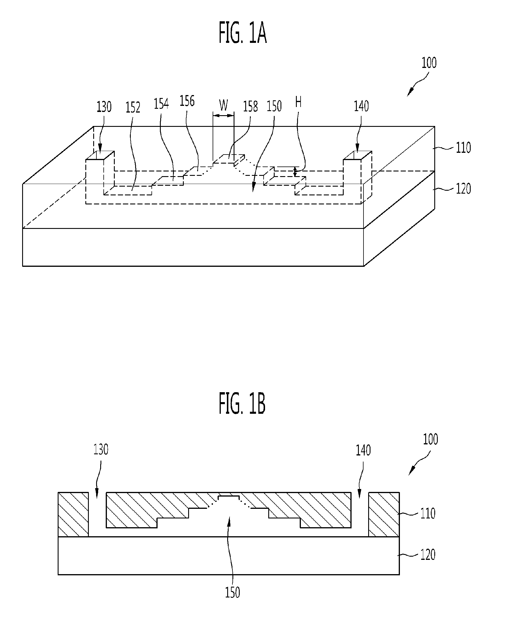
[0025]FIGS. 1A and 1B illustrate a structure of a microfluid control device according to an exemplary embodiment of the present invention. FIG. 1A is a perspective view and FIG. 1B is a cross-sectional view taken along line I-I′ of FIG. 1A.

[0026]As shown in FIGS. 1A and 1B, the microfluid control device 100 a...


PUM

PropertyMeasurementUnit
Widthaaaaaaaaaa
Depthaaaaaaaaaa
Forceaaaaaaaaaa

Abstract

Provided are a plastic microfluid control device having a multi-step microchannel and a method of manufacturing the same. The device includes a lower substrate, and a fluid channel substrate contacting the lower substrate and having a multi-step microchannel having at least two depths in a side coupling to the lower substrate. Thus, the device can precisely control the fluid flow by controlling capillary force in a depth direction of the channel by controlling the fluid using the multi-step microchannel having various channel depths. A multi-step micropattern is formed by repeating photolithography and transferred, thereby easily forming the multi-step microchannel having an even surface and a precisely controlled height.

Description

CROSS-REFERENCE TO RELATED APPLICATION[0001]This application claims priority to and the benefit of Korean Patent Application Nos. 10-2010-0026154 filed Mar. 24, 2010, and 10-2010-0077699 filed Aug. 12, 2010, the disclosure of which is incorporated herein by reference in its entirety.BACKGROUND[0002]1. Field of the Invention[0003]The present invention relates to a microfluid control device and a method of manufacturing the same, and more particularly, to a plastic microfluid control device having multi-step microchannels and a method of manufacturing the same.[0004]2. Discussion of Related Art[0005]Microfluid control devices are key components for a lab-on-a-chip, and are applied to various devices such as protein chips, DNA chips, drug delivery systems, micro total analysis systems, and micro reactors, which require precise fluid control.[0006]Depending on a method of controlling a microfluid, a microfluid control device may be implemented using a microactuating method for implement...

Claims


Application Information

Patent Timeline
IPC IPC(8): B01L3/00B32B37/02B32B37/12B29C65/06B32B38/06B32B38/00B29C33/38
CPCB01L3/502707Y10T29/494B01L3/502746B01L2300/0819B01L2300/161B29C33/3878B29C65/02B29C65/08B29C65/486B29C65/5057B29C66/53461B29L2031/756B32B37/12B32B38/06B32B2309/10B32B2310/028B32B2535/00B81B2201/058B81B2203/0338B81B2203/0392B81C1/00103F04B19/006B29C65/4845B29C65/4865B29C65/48B29C65/4825Y10T156/1039B01L3/50273
Inventor LEE, DAE SIKSONG, HYUN WOOCHUNG, KWANG HYOPARK, SEON HEEJUNG, MOON YOUNKIM, SEUNG HWAN
Owner ELECTRONICS & TELECOMM RES INST
Features
  • Generate Ideas
  • Intellectual Property
  • Life Sciences
  • Materials
  • Tech Scout
  • Unparalleled Data Quality
  • Higher Quality Content
  • 60% Fewer Hallucinations
Learn More