Hydrodynamic Coupling Arrangement, In Particular A Torque Converter

Active Publication Date: 2011-10-06
ZF FRIEDRICHSHAFEN AG
View PDF5 Cites 33 Cited by
  • Summary
  • Abstract
  • Description
  • Claims
  • Application Information

AI Technical Summary

Benefits of technology

[0025]The flow guide element can have, for example, a toothing projection that engages in the driven member and carries the outer toothing. For reasons of stability and ease of manufacture, the toothing projection can preferably be constructed annularly.
[0026]To ensure that the region in which the driven member adjoins the flow guide element can be used for flow guidance, it is further proposed that the inner toothing and the outer toothing e

Problems solved by technology

Rotational irregularities occurring in operation can excite vibrations in the powertrain which in turn result, for example, in the occurrence of rattling noises in the passenger compartment of the motor vehicle.
However, the rotational irregularities occurring in the powertrain are not uniformly distributed, but rather have order

Method used


Image

  • Hydrodynamic Coupling Arrangement, In Particular A Torque Converter
  • Hydrodynamic Coupling Arrangement, In Particular A Torque Converter
  • Hydrodynamic Coupling Arrangement, In Particular A Torque Converter

Examples


Example

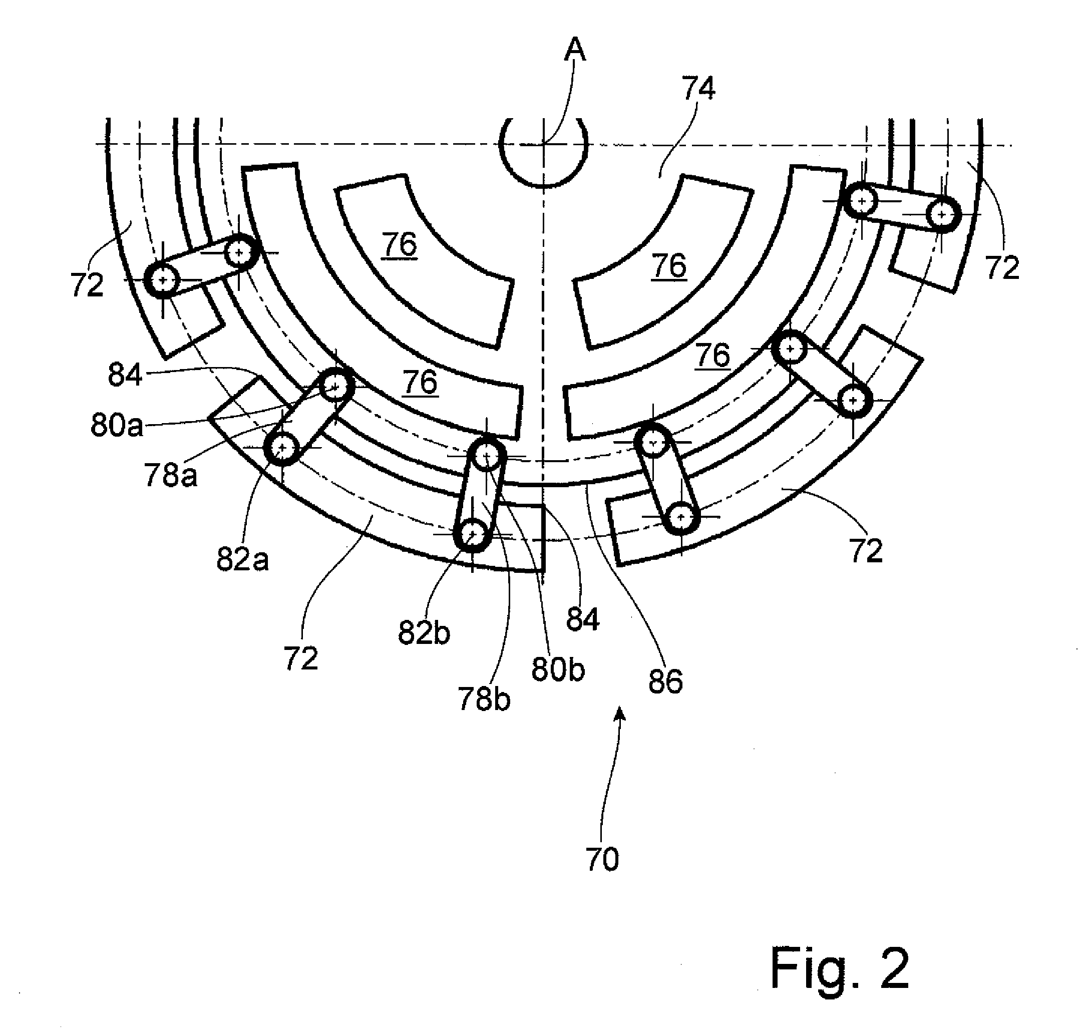
[0051]An axial view of a first embodiment form of the second damper arrangement 70 shown in FIG. 2 has a plurality of deflection masses 72 which are arranged successively at regular intervals around the axis of rotation A. Each of the deflection masses 72 is coupled by a first coupling element 78a and a second coupling element 78b to the deflection mass carrier 74 which has a plurality of openings 76 arranged successively in circumferential direction in order to economize on weight. The first coupling element 78a is rotatably coupled to the deflection mass carrier 70 in a first radially inner coupling area by a coupling bolt 8a; the second coupling element 78b is rotatably coupled to the deflection mass carrier 70 in a second radially inner coupling area located at a distance from the first radially inner coupling area in circumferential direction by a coupling bolt 80b shown in FIG. 2. Further, the first coupling element 78a is rotatably coupled to the deflection mass 72 associated...

Example

[0053]A second embodiment form of a second damper arrangement 170 is shown in FIG. 3. A deflection mass carrier 174 which, like deflection mass carrier 74, can be connected to the driven member 66 of the hydraulic torque converter 10 so as to be fixed with respect to rotation relative to it and which in order to economize on material has a plurality of openings 176 successively in circumferential direction is coupled to a deflection mass 172 by two coupling areas 178a and 178b.

[0054]The coupling area 178a illustrated in FIG. 3 is shown in an enlarged view in FIG. 4. A first guide path arrangement 182 in the deflection mass carrier 174 with vertex region 184 located on the radially outer side is movably coupled by a coupling bolt 180 to a second guide path arrangement 186 in the deflection mass 172 with vertex region 188 on the radially inner side. The coupling bolt 180 is movable along the first guide path arrangement 182 and the second guide path arrangement 186 and is guided by t...


PUM


Abstract

A hydrodynamic coupling includes a housing coupled to a driveshaft having an impeller and a turbine wheel is arranged in the housing driven by the impeller, and a first damper arrangement by which the housing is coupled to a driven member by a lockup clutch. The first damper arrangement includes a first torsional vibration damper connected to the lockup clutch is rotatable around an axis of rotation against the action of a first damper spring arrangement. A second torsional vibration damper is connected to the first torsional vibration damper and rotatable around the axis of rotation against the action of a second damper spring arrangement. The turbine wheel is connected to an intermediate torsional vibration damper region including a first secondary side, a second primary side, a second damper arrangement having a deflection mass carrier connected to the second secondary side that is carried at the deflection mass carrier such that a radial position of the deflection mass.

Description

PRIORITY CLAIM[0001]This is a U.S. national stage of Application No. PCT / EP2009 / 066487, filed on Dec. 7, 2009, which claims priority to German Application No: 10 2008 054 461.2, filed: Dec. 10, 2008, and German Application No. 10 2009 002 481.6, filed Apr. 20, 2009, the contents of which are incorporated herein by reference.BACKGROUND OF THE INVENTION[0002]1. Field of the Invention[0003]The present invention is directed to a hydrodynamic coupling arrangement, in particular a torque converter, comprising a housing be coupled to a driveshaft having an impeller, a turbine wheel arranged in an interior space of the housing driven by the impeller, and a first damper arrangement by which the housing can be coupled to a driven member by a lockup clutch. The first damper arrangement comprises a first torsional vibration damper having a first primary side connected to the lockup clutch and a first secondary side which is rotatable with respect to the first primary side around an axis of rota...

Claims


Application Information

Patent Timeline
IPC IPC(8): F16H45/02F16F15/139
CPCF16F15/145F16H45/02F16H2045/0226F16H2045/0278F16H2045/0247F16H2045/0263F16H2045/0231
Inventor HEULER, MICHAELREDIGER, PATRICKKENSY, MARIOSTROM, ALEXANDER
Owner ZF FRIEDRICHSHAFEN AG
Why Eureka
Try Eureka