Stylus

Inactive Publication Date: 2011-10-06
SHENZHEN FUTAIHONG PRECISION IND CO LTD +1
View PDF2 Cites 7 Cited by
  • Summary
  • Abstract
  • Description
  • Claims
  • Application Information

AI Technical Summary

Problems solved by technology

However, the conventional condenser-type styluses associated with such devices are complicated in structure and therefore costly to manufacture.

Method used


Image

  • Stylus
  • Stylus
  • Stylus

Examples


Embodiment Construction

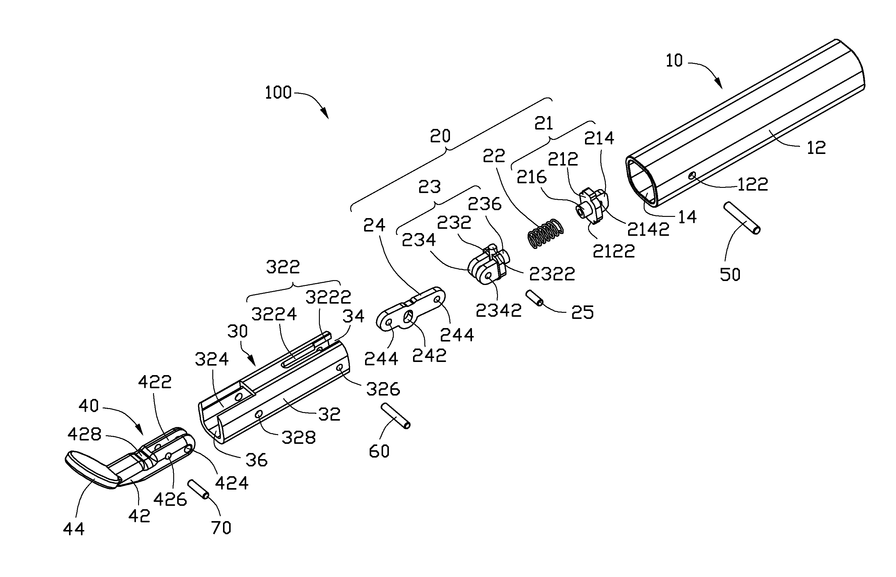
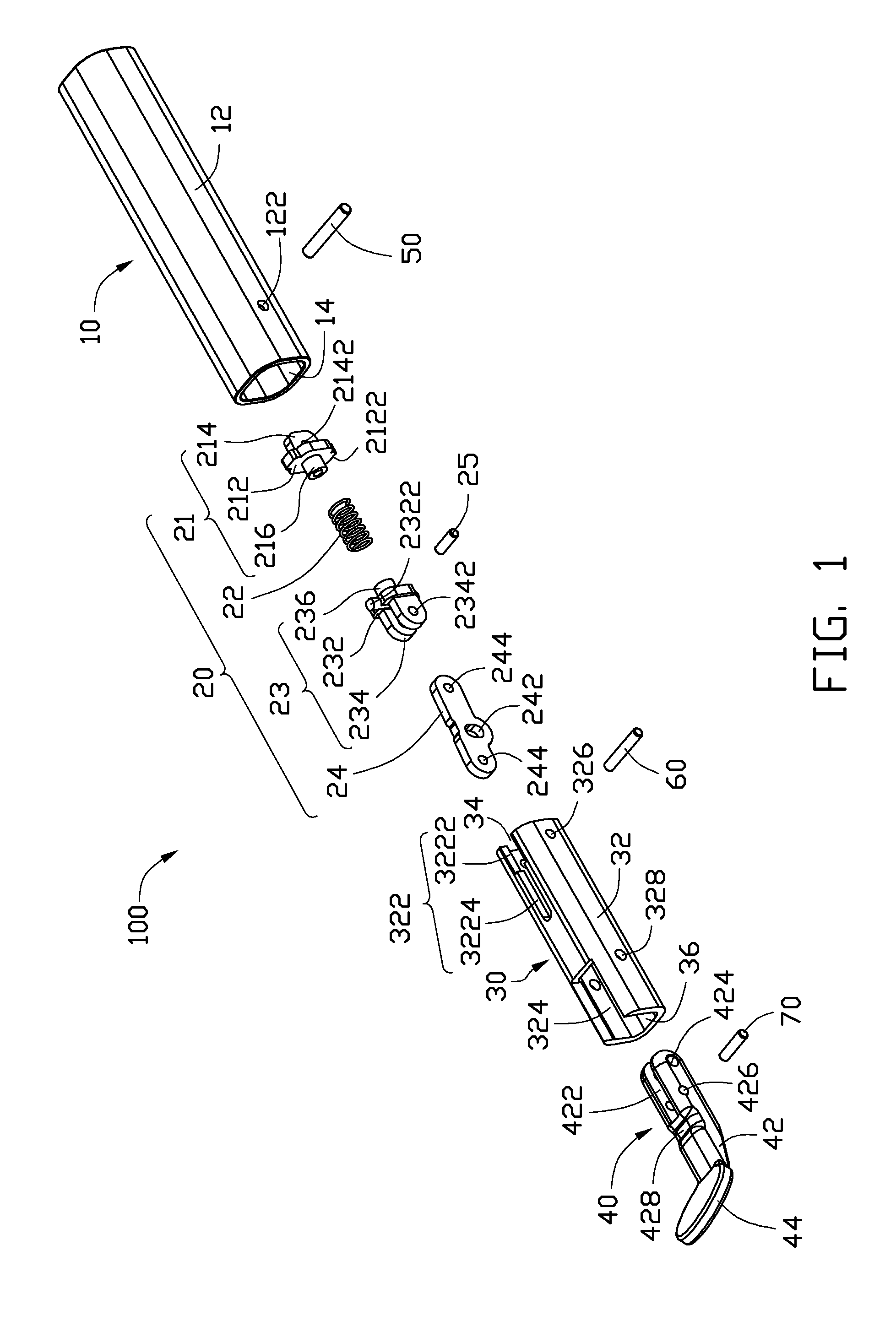
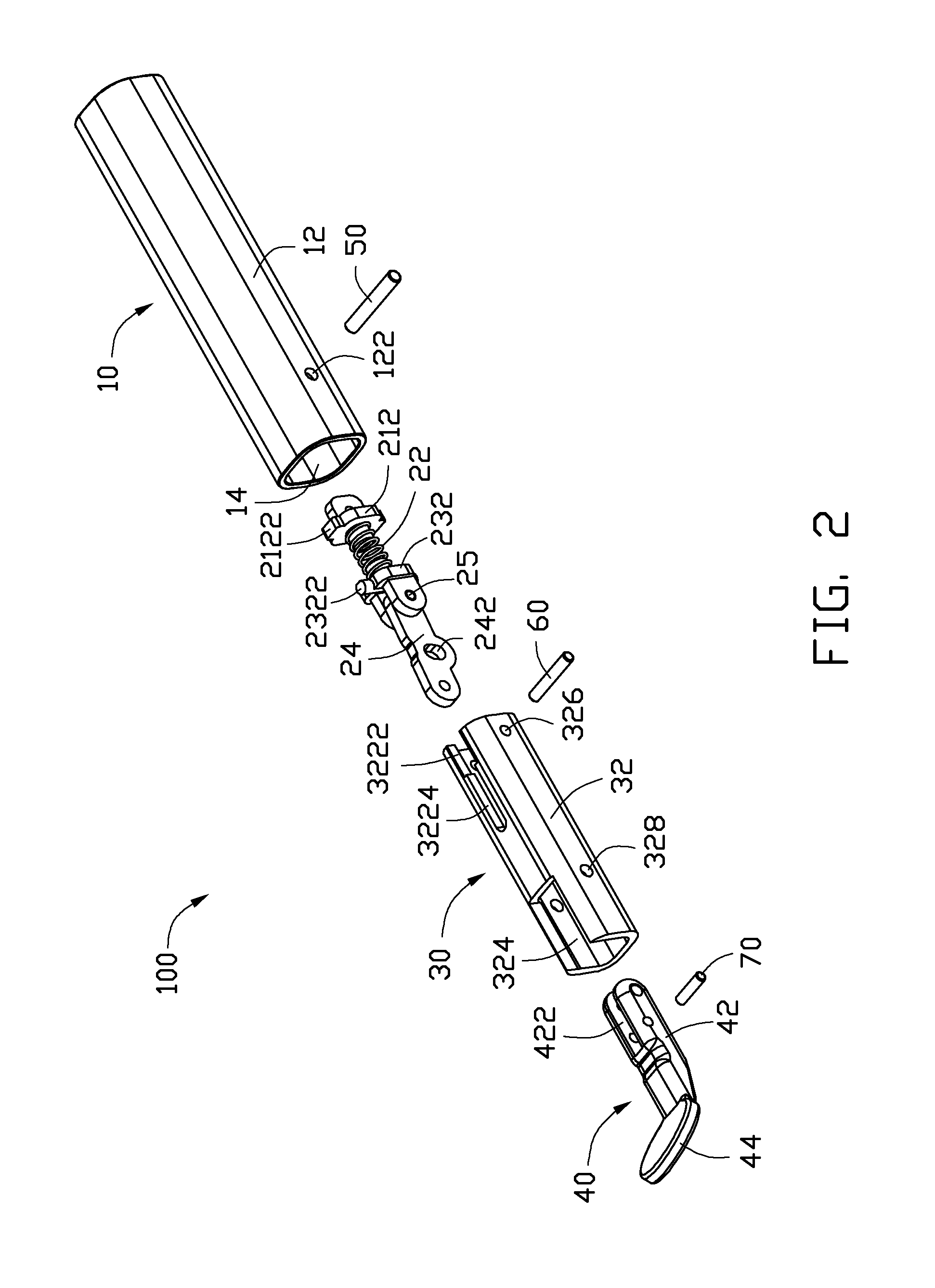
[0012]FIG. 1 shows an exemplary embodiment of a stylus 100 used in a portable electronic device such as a mobile phone, or a personal digital assistant (PDA). The stylus 100 includes a stylus barrel 10, a rod assembly 20, a sleeve 30, a stylus head 40, a shaft 50 and several connecting pins. The rod assembly 20 and the stylus head 40 are assembled in the sleeve 30, and the sleeve 30 is assembled in the stylus barrel 10. The stylus head 40 is mechanically connected forming an electrically conductive connection with the stylus barrel 10 and an end of the stylus head 40 extends out of the stylus barrel 10, to make sure the stylus head 40 electrically conducting with the body of user when using.

[0013]The stylus barrel 10 has an open end and an opposite closed end, and further includes a barrel wall 12, a receiving chamber 14 and a stop flange 16 (shown in FIG. 4). The stop flange 16 is annularly formed in the internal surface of the barrel wall 12, abutting the closed end. The barrel wa...


PUM


Abstract

A stylus includes a stylus barrel, a electrically conductive stylus head connecting to the stylus barrel, a rod assembly and a shaft. The rod assembly includes a swing block and an elastic member connecting the end of the swing block. The rod assembly is assembled in stylus barrel, the shaft is secured on the stylus barrel and passes through the swing block, making the swing block enable to tilt about the shaft, an end of the stylus head rotatably connects the other end of the swing block relative to the elastic member, the other end of the stylus head exposed to the stylus barrel, the elastic member provides an elastic force to cause the stylus head return to the original position after the stylus is moved into a tilted position.

Description

BACKGROUND[0001]1. Technical Field[0002]The present disclosure relates to styluses, and particularly, to a stylus used in portable electronic devices.[0003]2. Description of the Related Art[0004]With the development of wireless communication and information processing technologies, portable electronic devices, such as mobile phones and personal digital assistants (PDAs), employing touch screens are now in widespread use. The styluses are commonly used for writing against the touch screen of the electronic device. Especially, condenser-type styluses are employed widespread, the condenser-type stylus needs to electronically conduct with body of user for forming an electronic field in the electronic device when using the stylus, making the electronic device enable to detect the writing signal of the stylus. However, the conventional condenser-type styluses associated with such devices are complicated in structure and therefore costly to manufacture.[0005]Therefore, there is room for im...

Claims


Application Information

Patent Timeline
IPC IPC(8): G06F3/033
CPCG06F3/044G06F3/03545
Inventor LIANG, SHI-XUSA, CHUNG-YEH
Owner SHENZHEN FUTAIHONG PRECISION IND CO LTD
Why Eureka
Try Eureka