Surface wave antenna mountable on existing conductive structures

a surface wave antenna and conductive structure technology, applied in the field of communication, can solve the problems of requiring destruction or modification of existing architectural elements, such as walls, ceilings, or other architectural features, and difficult and costly installation of wireless repeater systems and associated antenna structures and interconnections

Active Publication Date: 2012-08-07
T MOBILE INNOVATIONS LLC
View PDF9 Cites 625 Cited by
  • Summary
  • Abstract
  • Description
  • Claims
  • Application Information

AI Technical Summary

Problems solved by technology

Unfortunately, it can be difficult and costly to install wireless repeater systems and the associated antenna structures and interconnections.
For example, in buildings and other architectural structures, locating antennas and interconnect therein for use by wireless communication devices can require destruction or modification of existing architectural elements, such as walls, ceilings, or other architectural features.

Method used


Image

  • Surface wave antenna mountable on existing conductive structures
  • Surface wave antenna mountable on existing conductive structures
  • Surface wave antenna mountable on existing conductive structures

Examples


Embodiment Construction

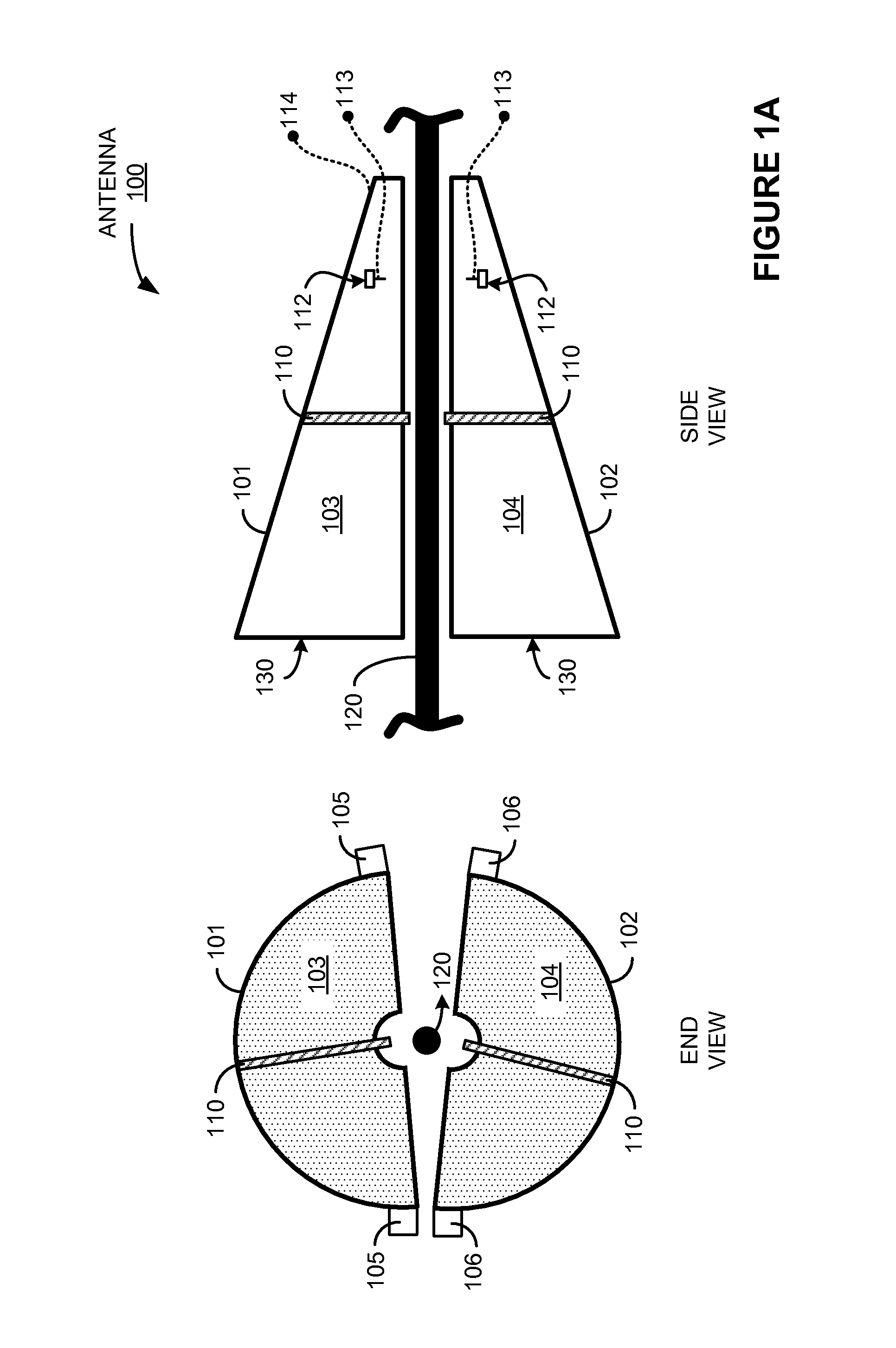
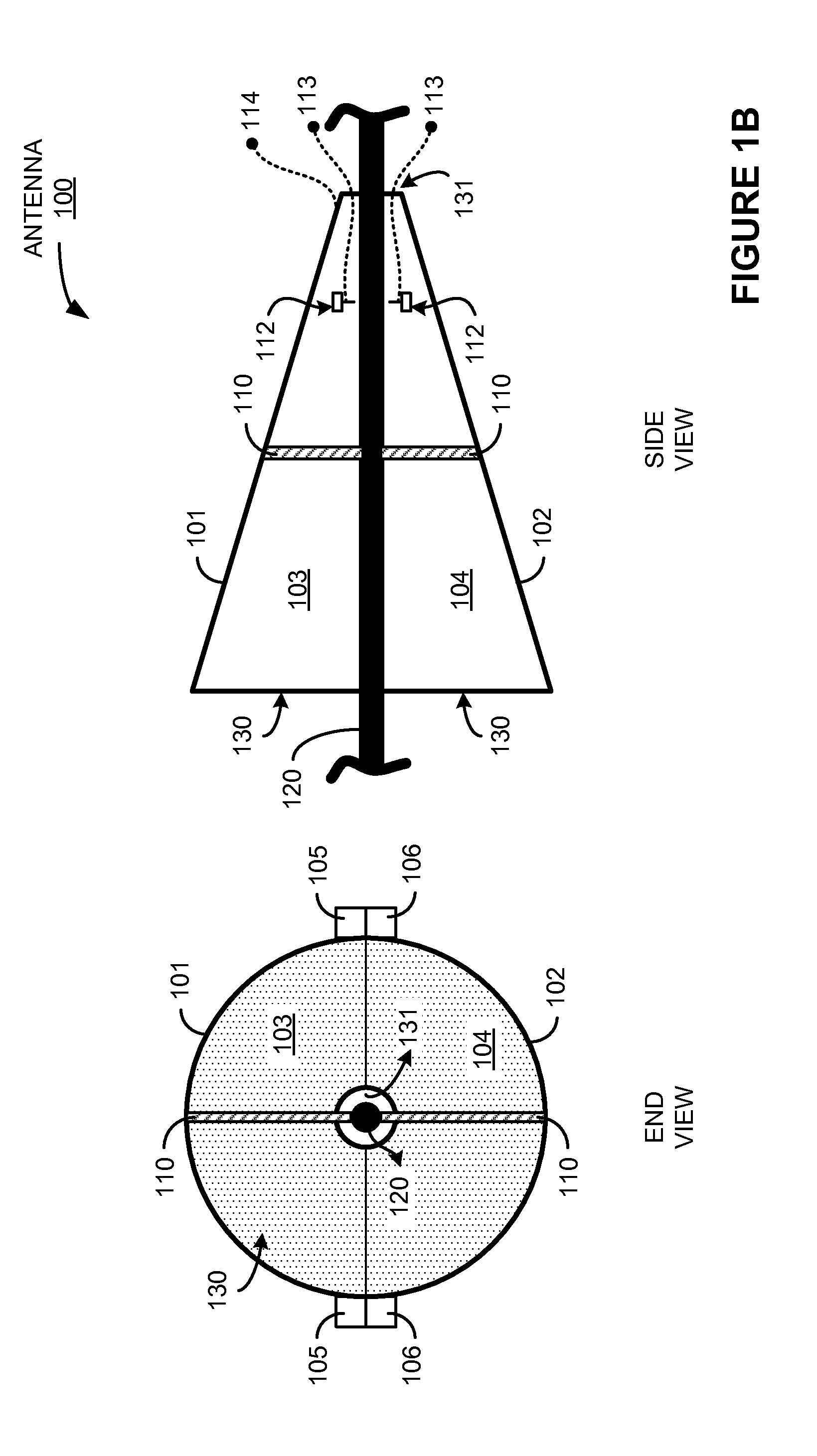
[0014]FIG. 1A is a schematic diagram in two views of a surface wave antenna. As shown in FIG. 1A, an end view and a side view of antenna 100 are included. Antenna 100 includes first portion 101, second portion 102, mounting element 110, and dipole element 112. FIG. 1A illustrates antenna 100 prior to attachment around electrically conductive structure 120. FIG. 1B, in contrast, illustrates antenna 100 after attachment around electrically conductive structure 120.

[0015]First portion 101 includes conductive element 103 and attachment element 105. Second portion 102 includes conductive element 104 and attachment element 106. Attachment elements 105 and 106 are not shown in the side view in FIG. 1A for clarity. Conductive element 103 and conductive element 104 are configured to each form a conductive longitudinal portion of a horn receive element. Conductive elements 103 and 104 could be comprised of any conductive material, such as metal, sheet metal, or other conductive material. Cond...


PUM


Abstract

What is disclosed is a surface wave antenna configured to install on an electrically conductive structure. The surface wave antenna includes a first portion comprising a conductive element and an attachment element, and a second portion comprising a conductive element and an attachment element. The conductive element of the first portion and the conductive element of the second portion are configured to each form a conductive longitudinal portion of a horn receive element, and the attachment elements are configured to conductively couple the conductive elements together to form the horn receive element. The surface wave antenna also includes a dipole element comprising a first transmit element and a second transmit element. The surface wave antenna also includes a mounting element comprising a first dielectric mount and a second dielectric mount.

Description

TECHNICAL FIELD[0001]Aspects of the disclosure are related to the field of communications, and in particular, surface wave antennas used in wireless communication systems.TECHNICAL BACKGROUND[0002]Wireless communication networks typically include wireless access nodes through which wireless communication devices communicate. Many times, the wireless communication devices are mobile, and move throughout areas of poor wireless communication coverage. In other examples, the wireless communication devices are located within buildings or other structures which can attenuate or degrade wireless communications between the wireless communication devices and the wireless access nodes.[0003]Wireless repeaters can be employed to enhance the wireless communication coverage of wireless access nodes for wireless communication devices. The wireless repeaters often retransmit the wireless communications of wireless access nodes for better reception by wireless communication devices. Likewise, the w...

Claims


Application Information

Patent Timeline
Patent Type & Authority Patents(United States)
IPC IPC(8): H01Q13/00
CPCH01Q13/26H01P3/10
Inventor JOHNSON, HAROLD WAYNEEULER, TIMOTHY D.
Owner T MOBILE INNOVATIONS LLC
Why Eureka
Try Eureka