Non-planar microstructures for manipulation of fluid samples

a microstructure and fluid sample technology, applied in flow mixers, sugar derivative preparations, electrolysis, etc., can solve the problems of inability to concentrate extracted materials, inability to achieve efficient prior art methods, and inability to integrate small analytical systems easily

Inactive Publication Date: 2002-04-09
CEPHEID INC
View PDF52 Cites 680 Cited by
  • Summary
  • Abstract
  • Description
  • Claims
  • Application Information

AI Technical Summary

Problems solved by technology

Prior art devices are generally not compatible with microfluidics nor easily integrated into small analytical systems.
None of the prior art methods is efficient nor able to concentrate extracted materials.
They must be designed to overcome microscale effects, such as low Reynolds numbers, that make conventional macroscopic design approaches ineffective.
However, it is well known that mixing of fluids in microfluidic systems is difficult.
The problem stems from the fact that the Reynolds numbers are typically so small (less than 100) in most microfluidic systems, that the flows are virtually always laminar.
Mixing by diffusion can be very slow.
In this approach, however, only two channels can be brought together and the total interfacial surface area is limited to the width and length of the channels in the mixing region.
In these cases, the total micromachined device area and cost will be increased.
However, conditions can be produced in the aqueous phase such that in most cases, limited only by extremes of salt concentration and pH or presence of denaturants or detergents, a lower Gibbs free energy state for the protein can be achieved in non-polar solvents, such as alcohols, various alkanes, and chloroform.
Over a very long period of time, the polar phase becomes depleted of proteins.
The presence of high salt concentration, detergents, phenol, and / or chaotropes can decrease the stability of the folded state of proteins in the polar phase.

Method used


Image

  • Non-planar microstructures for manipulation of fluid samples

Examples


example 2

The preceding Example teaches the production of structures with surfaces of bare silicon. To produce structures with insulating surfaces, such as silicon dioxide, a modified process is used.

The starting wafer is processed first through a thermal oxidation step to yield approximately 100 nm of oxide growth, and then coated with 100 nm of silicon nitride using low pressure chemical vapor deposition (LPCVD). The wafer is then processed through the photoresist patterning process described above in Example 1.

Before the DRIE etch, the nitride is etched using plasma etching (e.g. CF.sub.4 and O.sub.2), and then the oxide is etched using a buffered oxide etch (BOE). The wafer is then DRIE processed to produce the high aspect ratio structures. The photoresist is stripped, and the wafer is cleaned and further oxidized to produce an oxide on the sidewalls of the high aspect ratio structures with a thickness of 500 nm. The wafer is then put through a plasma etch process to remove the nitride on...


PUM

PropertyMeasurementUnit
depthaaaaaaaaaa
thickaaaaaaaaaa
thickaaaaaaaaaa

Abstract

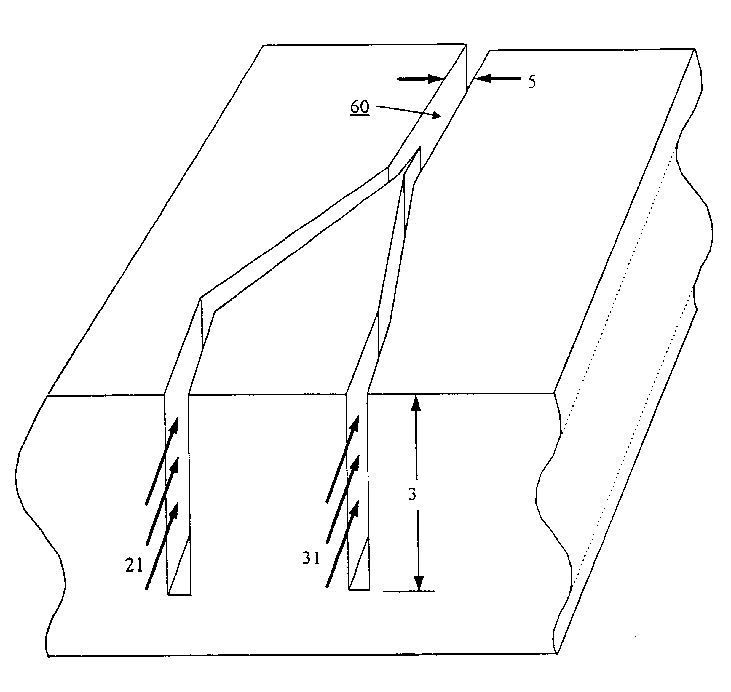
This invention comprises an apparatus and method for the manipulation of materials, including particles, cells, macromolecules, such as proteins, nucleic acids and other moieties, in fluid samples. The apparatus comprises an enclosed chamber on a chip having an internal microstructure with surface area substantially greater than the facial surface area of the internal structure. Generally the internal microstructure comprises a continuous network of channels, each of which has a depth substantially greater than its width. The network may comprise a single channel, a single channel with multiple branches, multiple channels, multiple channels with multiple branches, and any combination thereof. The internal structure may present an inert, non-reactive surface, or be coated with a reactive ligand, or be electrically conductive and optionally be coated with an electrical insulator. Discrete portions of the internal structure may differ in structural and surface properties. Multiple chips may be linked together to create a multiplexed array of chambers, optionally linked to other analytical devices.

Description

This invention relates to an apparatus and method for the manipulation of materials, including macromolecule s, such as proteins, nucleic acids and other moieties, in fluid samples.DESCRIPTION OF RELATED ARTSince Nobelist Richard Feynman first urged scientists and engineers in 1959 to pursue ultra-small technology, numerous devices have been described in the art for the miniaturization and minimalization of analytical systems.Austin et al. in U.S. Pat. No. 5,427,663 describe a microlithographic array for macromolecule and cell fractionation. This apparatus has channels of a depth commensurate in size to that of the microstructures in the fluid sample, so that the microstructures are restricted to flow in essentially a single layer. The use of traditional etching techniques limits the depth of the channels.Heller et al in PCT Publication No. WO 95 / 12808 describe a self addressable self-assembling microelectronic system and device which can actively carry out controlled multi-step and...

Claims


Application Information

Patent Timeline
Patent Type & Authority Patents(United States)
IPC IPC(8): B01F13/00B01L3/00B01J19/00B01F5/06B01F5/04C07H1/00G01N1/34
CPCB01F5/0403B01F13/0059B01J19/0093B01L3/502753C07H1/00B01F5/0645Y10T436/2575B01F2005/0031B01L2200/0636B01L2200/0668B01L2300/0681B01L2300/0816B01L2400/0415B01L2400/0487B01L2400/086G01N1/405G01N30/6095Y10S366/03B01F2025/9171B01F25/31B01F25/43231B01F33/30
Inventor CHRISTEL, LEE ALLANKOVACS, GREGORY T. A.MCMILLAN, WILLIAM A.NORTHRUP, M. ALLENPETERSEN, KURT E.POURAHMADI, FARZAD
Owner CEPHEID INC
Why Eureka
Try Eureka