
Analyte sensors and methods of manufacturing same

analyte sensor and sensor technology, applied in the field of analyte sensor and method of manufacturing same, can solve the problems of diabetics still not knowing whether their blood glucose value is increasing or decreasing based on conventional methods, many implantable glucose sensors suffer from complications within the body, and can cause dangerous side effects

Active Publication Date: 2011-02-03
DEXCOM
View PDF103 Cites 644 Cited by
  • Summary
  • Abstract
  • Description
  • Claims
  • Application Information

AI Technical Summary

Benefits of technology

[0206]In an embodiment of the eleventh aspect, the sensor system is configured for insertion near a joint of the host, and wherein the supporting member extends sufficiently from an exit site of the catheter to protect the elongated conductive body at a point of articulation of the joint.
[0207]In an embodiment of the eleventh aspect, the sensor system is configured for insertion near a joint of the host, and wherein the supporting member extends sufficiently from an exit site of the catheter to protect the elongated conductive body at a point of bending of the catheter.

Problems solved by technology

Due to the lack of comfort and convenience, a person with diabetes will often only measure his or her glucose level only two to four times per day when using a conventional SMBG monitor.
Unfortunately, these time intervals may be spread so far apart such that the diabetic may find out too late of a hyperglycemic or hypoglycemic event, thereby potentially incurring dangerous side effects.
Even if a diabetic manages to take a timely SMBG value, the diabetic may still not know whether his or her blood glucose value is increasing or decreasing based on conventional methods.
Heretofore, many implantable glucose sensors often suffer from complications within the body and provide only short-term or less-than-accurate measurement of blood glucose.
Similarly, conventional transdermal sensors can have problems in accurately measuring and reporting back glucose values continuously over extended periods of time.

Method used


Image

  • Analyte sensors and methods of manufacturing same
  • Analyte sensors and methods of manufacturing same
  • Analyte sensors and methods of manufacturing same

Examples


example

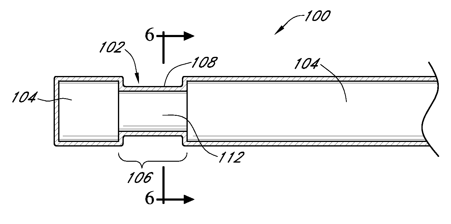
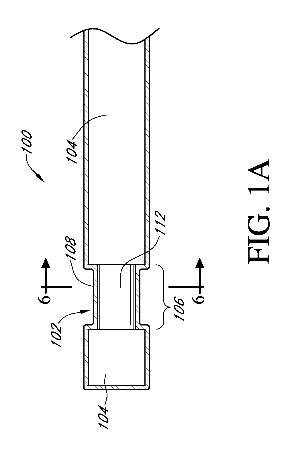
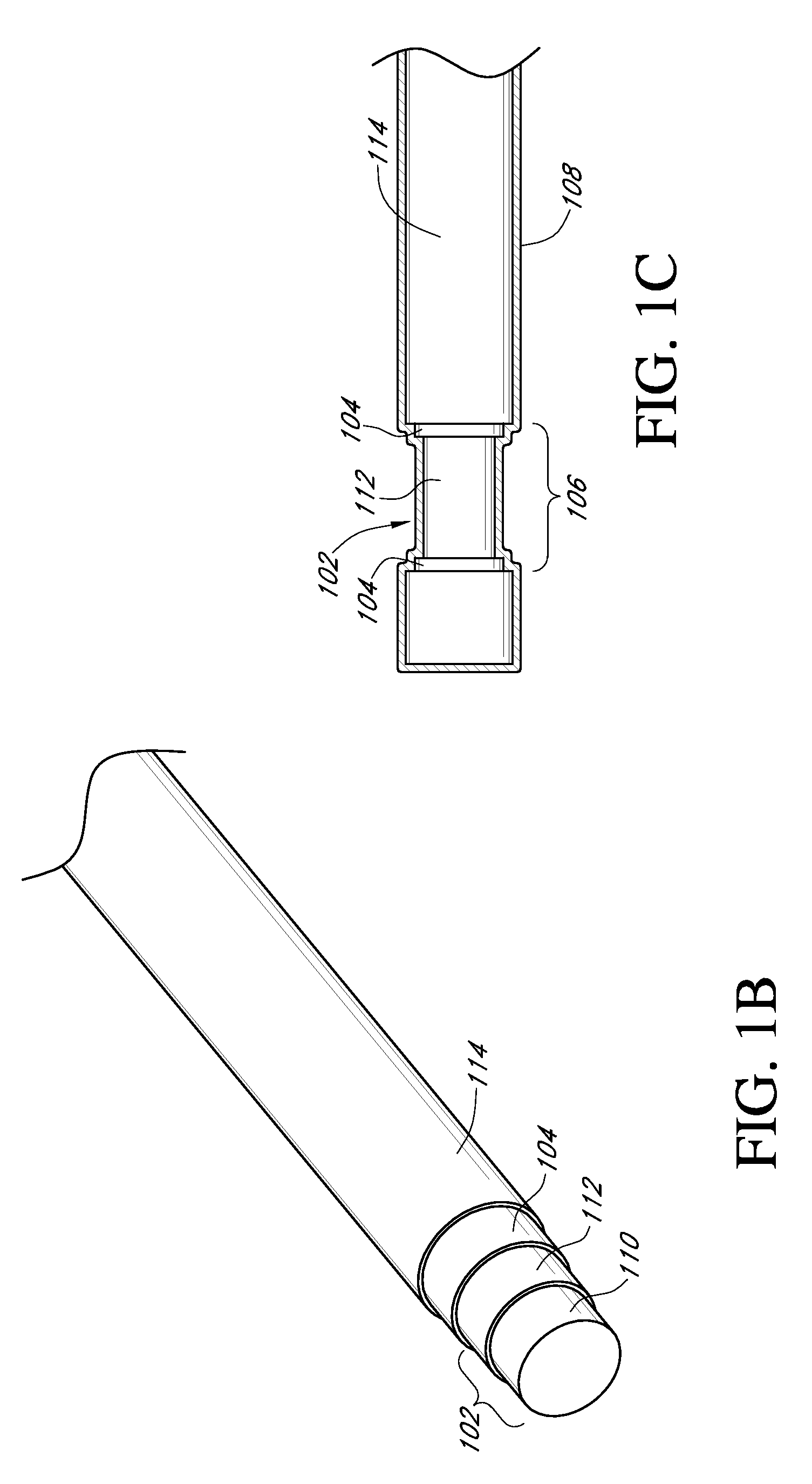
[0551]Test sensors were designed and fabricated with selection of certain materials, processing, and structure that improve fatigue life, and yet also improve comfort for the user. During the fabrication process, an elongated conductive body is first built by inserting / slip fitting a rod or wire into a tube formed of a conductive material, the combination of which forms an initial structure of an elongated conductive body. The resulting elongated conductive body is then passed through a series of dies to draw down the diameter of the elongated conductive body from a large diameter to a small diameter. With each pass through the die, the cross-sectional profile of the elongated conductive body is compressed, and the diameter associated therewith is reduced. Between passes through the die, an annealing step is performed to cause changes in the mechanical and structural properties of the elongated conductive body, and to relieve internal stresses, refine the structure by making it more...


PUM

PropertyMeasurementUnit
Young's modulusaaaaaaaaaa
particle sizeaaaaaaaaaa
cross-sectional radiusaaaaaaaaaa

Abstract

Analyte sensors and methods of manufacturing same are provided, including analyte sensors comprising multi-axis flexibility. For example, a multi-electrode sensor system 800 comprising two working electrodes and at least one reference / counter electrode is provided. The sensor system 800 comprises first and second elongated bodies E1, E2, each formed of a conductive core or of a core with a conductive layer deposited thereon, insulating layer 810 that separates the conductive layer 820 from the elongated body, a membrane layer deposited on top of the elongated bodies E1, E2, and working electrodes 802′, 802″ formed by removing portions of the conductive layer 820 and the insulating layer 810, thereby exposing electroactive surface of the elongated bodies E1, E2.

Description

CROSS-REFERENCE TO RELATED APPLICATIONS[0001]This application claims the benefit of priority under 35 U.S.C. §119(e) of U.S. Provisional Application No. 61 / 222,716 filed Jul. 2, 2009, U.S. Provisional Application No. 61 / 222,815 filed Jul. 2, 2009, and U.S. Provisional Application No. 61 / 222,751 filed Jul. 2, 2009, the disclosures of which are hereby expressly incorporated by reference in their entirety and are hereby expressly made a portion of this application.FIELD OF THE INVENTION[0002]The embodiments described herein relate generally to continuous analyte sensors and methods of manufacturing the sensors.BACKGROUND OF THE INVENTION[0003]Electrochemical sensors are useful in chemistry and medicine to determine the presence or concentration of a biological analyte. Such sensors are useful, for example, to monitor glucose in diabetic patients and lactate during critical care events.[0004]Diabetes mellitus is a disorder in which the pancreas cannot create sufficient insulin (Type I o...

Claims


Application Information

Patent Timeline
Patent Type & Authority Applications(United States)
IPC IPC(8): G01N27/00
CPCA61B5/14532A61B5/14865A61B2560/0223A61B2562/0209A61B5/1473A61B2562/125B05C3/10A61B5/1451A61B5/14517A61B2562/043B05C5/0241B05C3/125B05C3/02B05D1/18B05D3/06B23K26/0823B23K26/362B29C2791/009C23C2/00A61B5/14503A61B5/14546
Inventor SIMPSON, PETER C.BOOCK, ROBERTNEALE, PAUL V.BOHM, SEBASTIANWIGHTLIN, MATTHEWPRYOR, JACKMITCHELL, JASONJACKSON, JEFFPATEL, KAUSHIKLLEVARES, ANTONIO C.
Owner DEXCOM
Learn More